
Introductory Circuit Analysis (13th Edition)
13th Edition
ISBN: 9780133923605
Author: Robert L. Boylestad
Publisher: PEARSON
expand_more
expand_more
format_list_bulleted
Concept explainers
Videos
Textbook Question
Chapter 22, Problem 23P
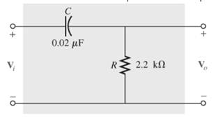
For the R-C high-pass filter in Fig. 22.108:
- Sketch
- versus frequency using a log scale for the frequency axis. Determine
- at
- one octave above and below fc and one decade above and below fc.
- Sketch the phase plot of
- versus frequency, where
- is the angle by which
- leads
- . Determine
- at the same frequencies noted in part (a).
Expert Solution & Answer
Want to see the full answer?
Check out a sample textbook solution
Students have asked these similar questions
of
it
H
PAGE 29
EEI-ELECTI CKTI FINALCOVERAGE
TOPIC AND ASSIGNMENT
SERIES RESONANCE (R, L&C CKTS)
WHERE:
I= CURRENT IN
AMPS
V:IMPRESSED
VOLTAGEN VOIS
aL R= RESISTANCEE
IN OH MS
L= INDUCTANCE
IN HENRY
C CAPACITANCE
IRLFARAD
FIGURE
RESONANT FREQUENCY
FORMULA
HZ
ASSIENMENT
PROBLEM:
AN IMPEDANCE COIL HAVING ARESISTANCE
AND INDUCTANCE OF 20 AND I.5 MILLLHENRY
RESPECTIVELY CONNECTED IN SERIES WITH
A CAPACITOR. CALCULATE THE VALUE OF
CAPACITANCE IFTHE CKT WILL OPERATE AT
RESONANCE.THE RESONANT EREQUENC(to
15 4.5 KHZ.
Assuming that a vi sine signal of variable frequency is applied to the image circuit, it is necessary to calculate its gain as a function of w. What will be the gain in decibels when R1 = R2 = 1MQ, C1 = C2 = 1μF and w = 10rad³/ s
103 rad / s? answers: Avf = -120dB
H.W:
A resistor of resistance R=1000 2is maintained at 17 °C and it shunted by 100 uH
inductor. Determine the ms noise voltage across the inductor over a frequency
bandwi dth of:
Ans: 182 x10° volt
Ans: 9.22 x10 volt
Ans: 2.34 x10 volt
i)
15.9 kHz
ii)
i)
159 kHz
1590 kHz
Chapter 22 Solutions
Introductory Circuit Analysis (13th Edition)
Ch. 22 - Determine the frequencies (in kHz) at the points...Ch. 22 - Determine log10 for each value of X. 100,000...Ch. 22 - Given N=log10 , determine for each value of N. 3...Ch. 22 - Determine loge for each value of X. a. 100,000 b....Ch. 22 - Determine log1048=log10(8)(6), and compare to...Ch. 22 - Determine log100.2=log1018/90, and compare to...Ch. 22 - Verify that log100.5 is equal to...Ch. 22 - Prob. 8PCh. 22 - Determine the number of bels that relate power...Ch. 22 - Prob. 10P
Ch. 22 - Prob. 11PCh. 22 - Determine the dBm level for an output power of...Ch. 22 - Find the dBu gain of an amplifier that raises the...Ch. 22 - Prob. 14PCh. 22 - If the sound pressure level is increased from...Ch. 22 - What is the required increase in acoustical power...Ch. 22 - Using semilog paper, plot XL versus frequency for...Ch. 22 - For the meter of Fig. 22.8, find the power...Ch. 22 - For the R-C low-pass filter in Fig. 22.105: Sketch...Ch. 22 - Prob. 20PCh. 22 - Design an R-Clow-pass filter to have a cutoff...Ch. 22 - For the low-pass filter in Fig. 22.107: Fig....Ch. 22 - For the R-C high-pass filter in Fig. 22.108:...Ch. 22 - For the network in Fig. 22.109: Determine...Ch. 22 - Design a high-pass R-C filter to have a cutoff or...Ch. 22 - For the high-pass filter in Fig. 22.110: Determine...Ch. 22 - For the band-pass filter in Fig. 22.111: Sketch...Ch. 22 - Design a band-pass filter such as the one...Ch. 22 - For the band-pass filter in Fig. 22.112...Ch. 22 - Prob. 30PCh. 22 - For the band-stop filter in Fig. 22.114: Determine...Ch. 22 - For the band-pass filter in Fig. 22.115: Determine...Ch. 22 - For the network in Fig. 22.45(a), if...Ch. 22 - Prob. 34PCh. 22 - For the low-pass T filter of Fig. 22.116: In...Ch. 22 - Prob. 36PCh. 22 - For the Butterworth filter of Fig. 22.118: Fig....Ch. 22 - Sketch the idealized Bode plot for Av=Vo/Vi for...Ch. 22 - Sketch the response of the magnitude of...Ch. 22 - Sketch the idealized Bode plot for Av=Vo/Vi for...Ch. 22 - Sketch the response of the magnitude of...Ch. 22 - Prob. 42PCh. 22 - Prob. 43PCh. 22 - For the filter in Fig. 22.125: Sketch the curve of...Ch. 22 - Prob. 45PCh. 22 - Prob. 46PCh. 22 - Prob. 47PCh. 22 - A bipolar transistor amplifier has the following...Ch. 22 - A transistor amplifier has a midband gain of 120,...Ch. 22 - Sketch the Bode plot of the following function:...Ch. 22 - Sketch the Bode plot of the following function:...Ch. 22 - Sketch the Bode plot of the following function:...Ch. 22 - Sketch the Bode plot of the following function:...Ch. 22 - Sketch the Bode plot of the following function...Ch. 22 - Prob. 56PCh. 22 - Using schematics, obtain the magnitude and phase...Ch. 22 - Using schematics, obtain the magnitude and phase...Ch. 22 - Prob. 59PCh. 22 - Prob. 60P
Knowledge Booster


Learn more about
Need a deep-dive on the concept behind this application? Look no further. Learn more about this topic, electrical-engineering and related others by exploring similar questions and additional content below.Similar questions
- Two resistor ,5 kohms and 20 kohms are at 27 degree C. Calculate the thermal noise voltage for a 10-kHz bandwidth if they are in seriesarrow_forward22: Answer one of the following a) Determine the transfer function of the following signal flow chart -k3arrow_forwardIm + Re -100 -1 Figure 1: We want to sketch the bode plot for this filter! 1) Rewrite H(s) in the "standard form" for Bode plots 2) Using paper + pencil, sketch the Bode magnitude and phase shift plots. 3) What kind of filter is this: Low-pass Bandpass High-pass Notcharrow_forward
- For the following filters' circuits: a) Find and draw H(j@) b) Specify what type of filter is this using qualitative analysisarrow_forwardWhat is the high pass filter cutoff frequency of the circuit R1= 54 Q, R2 = 261 Q, RF = 332 Q, RG = 8560 Q, C1 = 0.25 uF, C2 = 89 uF. Note: No need to place the unit, express your answer in Hz, two decimal places. ww RG RF ww m ww RG RF ww R2 Vin 다 C1 m R1 + C2 + Voutarrow_forwardSolve for the critical frequency of this Low Pass Filter a. 100 Hz b. 1kHzarrow_forward
- a. Given the Bode diagram in figure 2, obtain the following by showing horizontal and vertical line on the graph. i. gain cross over frequency ii. phase cross over frequency iii. Gain margin iv. Phase margin v. Comment on the stability of the system.arrow_forwardSeries RC low-pass filter, components are: R=5kN and C=0.005 µF and the amplitude of the source voltage is 5V peak-to-peak. a)Calculate the cut-off frequency in Hz. b)Calculate Vo in magnitude when the source voltage has frequencies of 0.4, 0.8, 1.2, 1.6, 2, 4, 8 kHz one by one.arrow_forward7. a. The bandwidth of a series resonant circuit is 200 Hz. If the resonant frequency is 2000 Hz, what is the value of Q. for the circuit? b. If R = 22, what is the value of X₂ at resonance? c. Find the value of L and C at resonance. d. Find the cutoff frequencies.arrow_forward
arrow_back_ios
SEE MORE QUESTIONS
arrow_forward_ios
Recommended textbooks for you
 Introductory Circuit Analysis (13th Edition)Electrical EngineeringISBN:9780133923605Author:Robert L. BoylestadPublisher:PEARSON
 Delmar's Standard Textbook Of ElectricityElectrical EngineeringISBN:9781337900348Author:Stephen L. HermanPublisher:Cengage Learning
 Programmable Logic ControllersElectrical EngineeringISBN:9780073373843Author:Frank D. PetruzellaPublisher:McGraw-Hill Education
 Fundamentals of Electric CircuitsElectrical EngineeringISBN:9780078028229Author:Charles K Alexander, Matthew SadikuPublisher:McGraw-Hill Education
 Electric Circuits. (11th Edition)Electrical EngineeringISBN:9780134746968Author:James W. Nilsson, Susan RiedelPublisher:PEARSON
 Engineering ElectromagneticsElectrical EngineeringISBN:9780078028151Author:Hayt, William H. (william Hart), Jr, BUCK, John A.Publisher:Mcgraw-hill Education,
Introductory Circuit Analysis (13th Edition)
Electrical Engineering
ISBN:9780133923605
Author:Robert L. Boylestad
Publisher:PEARSON
Delmar's Standard Textbook Of Electricity
Electrical Engineering
ISBN:9781337900348
Author:Stephen L. Herman
Publisher:Cengage Learning
Programmable Logic Controllers
Electrical Engineering
ISBN:9780073373843
Author:Frank D. Petruzella
Publisher:McGraw-Hill Education
Fundamentals of Electric Circuits
Electrical Engineering
ISBN:9780078028229
Author:Charles K Alexander, Matthew Sadiku
Publisher:McGraw-Hill Education
Electric Circuits. (11th Edition)
Electrical Engineering
ISBN:9780134746968
Author:James W. Nilsson, Susan Riedel
Publisher:PEARSON
Engineering Electromagnetics
Electrical Engineering
ISBN:9780078028151
Author:Hayt, William H. (william Hart), Jr, BUCK, John A.
Publisher:Mcgraw-hill Education,
What is Filter & Classification of Filters | Four Types of Filters | Electronic Devices & Circuits; Author: SimplyInfo;https://www.youtube.com/watch?v=9x1Sjz-VPSg;License: Standard Youtube License