Engineering Mechanics: Dynamics (14th Edition)
14th Edition
ISBN: 9780133915389
Author: Russell C. Hibbeler
Publisher: PEARSON
expand_more
expand_more
format_list_bulleted
Concept explainers
Videos
Textbook Question
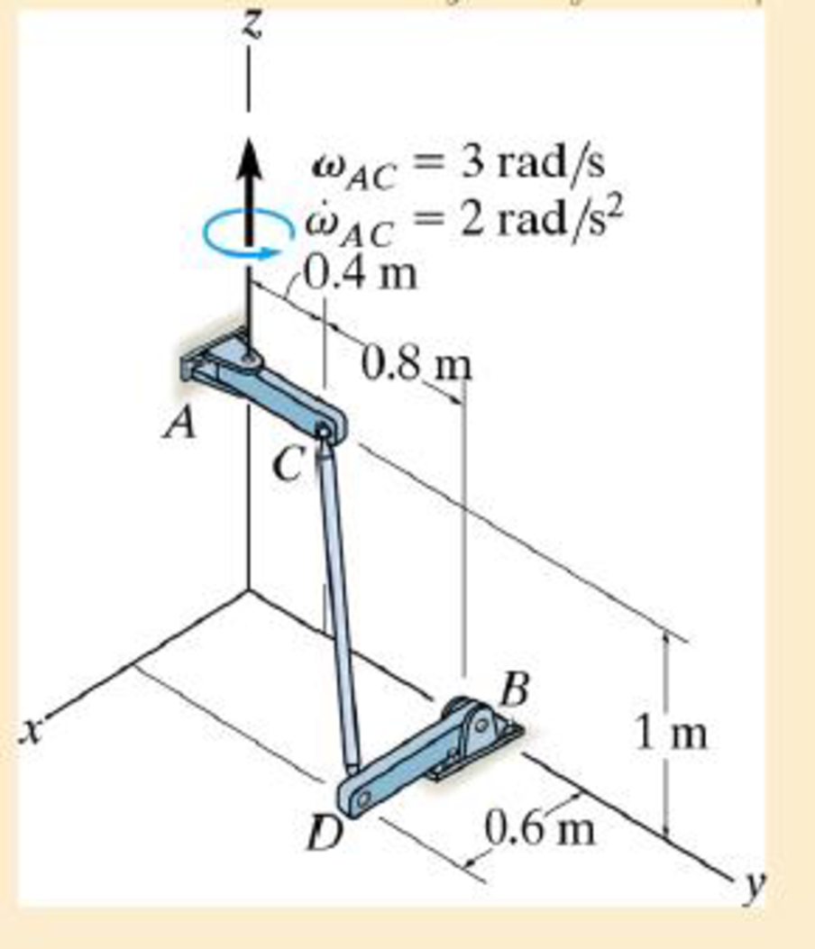
Chapter 20.3, Problem 34P
Rod CD is attached to the rotating arms using ball-and-socket joints. If AC has the motion shown, determine the angular acceleration of link BD at this instant.
Expert Solution & Answer
Want to see the full answer?
Check out a sample textbook solution
Students have asked these similar questions
Assignment 10, Question 4, Problem Book #202
Problem Statement
An ideal Brayton cycle with a two-stage compressor, a two-stage turbine, and a regenerator
operates with a mass flow rate of 25 kg/s. The regenerator cold inlet is at 490 K and its
effectiveness is 60%. Ambient conditions are 90 kPa and 20°C. The intercooler operates at
450 kPa and the reheater operates at 550 kPa. The temperature at the exit of the combustion
chamber is 1,400 K. Heat is removed in the intercooler at a rate of 2.5 MW and heat is added
in the reheater at a rate of 10 MW. Determine the thermal efficiency and the back work
ratio. Use a cold air standard analysis with cp = 1.005 kJ/(kg K) and k = 1.4.
.
Answer Table
Stage
Description
Your Answer
Correct
Answer
Due Date
Grade
(%)
1
Thermal efficiency (%)
Dec 5, 2024 11:59 pm
0.0
1
Weight Attempt Action/Message
1/5
Part
Type
Submit
1
Back work ratio (%)
Dec 5, 2024 11:59 pm
0.0
1
* Correct answers will only show after due date has passed.
Assignment 10, Question 3, Problem Book #198
Problem Statement
Consider a Brayton cycle with a regenerator. The regenerator has an effectiveness of 75%.
The compressor inlet conditions are 1.2 bar and 300 K and the mass flowrate is 4.5 kg/s. The
compressor outlet pressure is 9 bar. Both the compressor and turbine consist of a single
isentropic stage. What minimum power output must be achieved before the regenerator
begins to have a benefit? Use an air-standard analysis.
Answer Table
Correct Answer
Stage
Description
Your Answer
Due Date
Grade
(%)
Part
Weight Attempt Action/Message
Туре
1
Power output (MW)
Dec 5, 2024 11:59 pm
0.0
1
1/5
Submit
* Correct answers will only show after due date has passed.
Q-3 Consider an engine operating on the ideal Diesel cycle with air as the
working fluid. The volume of the cylinder is 1200 cm³ at the beginning of the
Compression process, 75 cm³ at the end, and 150 cm³ after the heat addition
process. Air is at 17°c and lookpa at the beginning of the compression proc
ess. Determine @ The pressure at the beginning of the heat rejection
process. the net work per cycle in kjⒸthe mean effective pressur.
Answers @264.3 KN/m² ②0.784 kj or 544-6 kj © 697 KN
19
2
m
Chapter 20 Solutions
Engineering Mechanics: Dynamics (14th Edition)
Ch. 20.3 - Prob. 1PCh. 20.3 - Prob. 2PCh. 20.3 - Prob. 3PCh. 20.3 - Prob. 4PCh. 20.3 - Prob. 5PCh. 20.3 - Prob. 6PCh. 20.3 - Prob. 7PCh. 20.3 - The disk rotates about the shaft S, while the...Ch. 20.3 - The electric fan is mounted on a swivel support...Ch. 20.3 - Prob. 11P
Ch. 20.3 - Prob. 12PCh. 20.3 - The right circular cone rotates about the z axis...Ch. 20.3 - Prob. 14PCh. 20.3 - Prob. 15PCh. 20.3 - Prob. 16PCh. 20.3 - Prob. 17PCh. 20.3 - Prob. 18PCh. 20.3 - Prob. 20PCh. 20.3 - Prob. 21PCh. 20.3 - Prob. 22PCh. 20.3 - Prob. 23PCh. 20.3 - Prob. 24PCh. 20.3 - Prob. 25PCh. 20.3 - Rod AB is attached to collars at its ends by using...Ch. 20.3 - Rod AB is attached to collars at its ends by using...Ch. 20.3 - If the rod is attached with ball-and-socket joints...Ch. 20.3 - Prob. 29PCh. 20.3 - If collar A has a speed vA = 4 m/s, determine the...Ch. 20.3 - Prob. 31PCh. 20.3 - If the collar A in Prob. 20-31 has a deceleration...Ch. 20.3 - Prob. 33PCh. 20.3 - Rod CD is attached to the rotating arms using...Ch. 20.3 - Prob. 35PCh. 20.3 - Prob. 36PCh. 20.4 - So1ve Example 20.5 such that the x, y, z axes move...Ch. 20.4 - Prob. 38PCh. 20.4 - Prob. 39PCh. 20.4 - At the instant = 60, the construction lift is...Ch. 20.4 - Prob. 41PCh. 20.4 - Prob. 42PCh. 20.4 - Prob. 43PCh. 20.4 - Prob. 44PCh. 20.4 - Prob. 45PCh. 20.4 - Prob. 46PCh. 20.4 - Prob. 47PCh. 20.4 - At the given instant the rod is turning about the...Ch. 20.4 - Prob. 49PCh. 20.4 - Prob. 50PCh. 20.4 - Prob. 51PCh. 20.4 - Prob. 52PCh. 20.4 - Prob. 53PCh. 20.4 - At the instant shown, the arm AB is rotating about...
Knowledge Booster


Learn more about
Need a deep-dive on the concept behind this application? Look no further. Learn more about this topic, mechanical-engineering and related others by exploring similar questions and additional content below.Similar questions
- In the system shown in the (img 1), water flows through the pump at a rate of 50L/s. The permissible NPSH providedby the manufacturer with that flow is 3.6 m. Determine the maximum height Delta z above the water surface at which the Pump can be installed to operate without cavitation. Include all losses in the suction tube. What is the value of the smaller total losses? What is the value of minor-minor losses? What is the value of major-minor losses?arrow_forwardA plastic canister whose bottom surface can be approximated as a flat surface1.9 m and 3 m long, travels through the water at 19 °C with a speed of up to 48 km/h. Determine: Drag due to friction that water exerts on the boat The power needed to overcome itarrow_forward(Fig. 1) shows the performance of a centrifugal pump for various diameters of theimpeller. For such a pump with a 5" diameter impeller, what power, in hp, would be expected to supply 5 L/s?what is its efficiency, in %?A pumping system requires 6 L/s of water with a load of 8 m, which of the pumpsof (fig. 1) would you recommend for this application?;arrow_forward
- You have the following information about a ship (image 1) Determine:a) Calculation of the block coefficient. b) Calculation of the wake coefficient. c) Determine the length of the wake.arrow_forwardA stainless steel canoe moves horizontally along the surface of a lake at 3.7 mi/h. TheThe lake's water temperature is 60°F. The bottom of the canoe is 25 ft long and flat. The boundary layer inThe bottom of the canoe is laminar or turbulent. the value of kinematic viscosity is? the value of the Reynolds number is?arrow_forwardExample Example 1 A vertical tubular test section is to be installed in an experimental high pressure water loop. The tube is 10.16 mm i.d. and 3.66 m long heated uniformly over its EXAMPLE 73 length. An estimate of the pressure drop across the test section is required as a function of the flow-rate of water entering the test section at 204°C and 68.9 bar. (1) Calculate the pressure drop over the test section for a water flow of 0.108 kg/s with a power of 100 kW applied to the tube using (i) the homogeneous model (ii) the Martinelli-Nelson model (iii) The Thom correlation (iv) the Baroczy correlation (2) Estimate the pressure drop versus flow-rate relationship over the range 0.108 to 0.811 kg/s (2-15 USGPM) for a power of 100 kW and 200 kW applied to the tube using (i) the Martinelli-Nelson model (ii) the Baroczy correlationarrow_forward
- "A seismograph detects vibrations caused by seismic movements. To model this system, it is assumed that the structure undergoes a vibration with a known amplitude band frequency w (rad/s), such that its vertical displacement is given by xB=bsin(wt). This movement of the structure will produce a relative acceleration in the mass m of 2 kg, whose displacement 2 will be plotted on a roller." x= 15 kN/m Structure -WI 24 mm (Ctrl) sin(wt) b(w/w)² √√1 (w/w)] + [25(w/w)]²' "The seismograph's roller measures 60 mm, and a maximum vibration amplitude of the structure of b<5 mm is expected. Design the damper (constant c) to ensure that, for a constant oscillation, the seismograph functions correctly and the needle does not move off the roller."arrow_forwardAircraft B is traveling at a steady speed of VB = 400 mi/hr at an altitude of 6000 ft. Meanwhile, when aircraft A is at an altitude of 10,000 ft, the line connecting A to B lies in the vertical plane of B's flight path and forms an angle of 0 = 30 degrees with the vertical. Assuming A maintains a constant velocity, find the speed required for a collision to occur. Additionally, calculate the time it would take for the collision to happen after both aircraft reach the described positions, provided no evasive measures are taken. Problem outline: 1- Find the velocity of A for the collision to happen. 2- Find the time at which the collision happens. 3- Explain the solution process with your own words. - 10,000 ft 12° 6000 ft B UBarrow_forwardDetermine the gross take-off weight of the aircraftarrow_forward
arrow_back_ios
SEE MORE QUESTIONS
arrow_forward_ios
Recommended textbooks for you
 Elements Of ElectromagneticsMechanical EngineeringISBN:9780190698614Author:Sadiku, Matthew N. O.Publisher:Oxford University Press
 Mechanics of Materials (10th Edition)Mechanical EngineeringISBN:9780134319650Author:Russell C. HibbelerPublisher:PEARSON
 Thermodynamics: An Engineering ApproachMechanical EngineeringISBN:9781259822674Author:Yunus A. Cengel Dr., Michael A. BolesPublisher:McGraw-Hill Education
 Control Systems EngineeringMechanical EngineeringISBN:9781118170519Author:Norman S. NisePublisher:WILEY
 Mechanics of Materials (MindTap Course List)Mechanical EngineeringISBN:9781337093347Author:Barry J. Goodno, James M. GerePublisher:Cengage Learning
 Engineering Mechanics: StaticsMechanical EngineeringISBN:9781118807330Author:James L. Meriam, L. G. Kraige, J. N. BoltonPublisher:WILEY
Elements Of Electromagnetics
Mechanical Engineering
ISBN:9780190698614
Author:Sadiku, Matthew N. O.
Publisher:Oxford University Press
Mechanics of Materials (10th Edition)
Mechanical Engineering
ISBN:9780134319650
Author:Russell C. Hibbeler
Publisher:PEARSON
Thermodynamics: An Engineering Approach
Mechanical Engineering
ISBN:9781259822674
Author:Yunus A. Cengel Dr., Michael A. Boles
Publisher:McGraw-Hill Education
Control Systems Engineering
Mechanical Engineering
ISBN:9781118170519
Author:Norman S. Nise
Publisher:WILEY
Mechanics of Materials (MindTap Course List)
Mechanical Engineering
ISBN:9781337093347
Author:Barry J. Goodno, James M. Gere
Publisher:Cengage Learning
Engineering Mechanics: Statics
Mechanical Engineering
ISBN:9781118807330
Author:James L. Meriam, L. G. Kraige, J. N. Bolton
Publisher:WILEY
Dynamics - Lesson 1: Introduction and Constant Acceleration Equations; Author: Jeff Hanson;https://www.youtube.com/watch?v=7aMiZ3b0Ieg;License: Standard YouTube License, CC-BY