Elements Of Electromagnetics
7th Edition
ISBN: 9780190698614
Author: Sadiku, Matthew N. O.
Publisher: Oxford University Press
expand_more
expand_more
format_list_bulleted
Concept explainers
Question
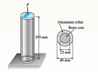
A cylindrical assembly consisting of a brass
core and an aluminum collar is compressed by a load
P (see figure). The length of the aluminum collar
and brass core is 350 mm, the diameter of the core
is 25 mm, and the outside diameter of the collar is
40 mm. Also, the moduli of elasticity of the aluminum
and brass are 72 GPa and 100 GPa, respectively.
(a) If the length of the assembly decreases by 0.1%
when the load P is applied, what is the magnitude
of the load?
(b) What is the maximum permissible load Pmax if
the allowable stresses in the aluminum and brass
are 80 MPa and 120 MPa, respectively?

Transcribed Image Text:Aluminum collar
Brass core
350 mm
25 mm
40 mm
Expert Solution
This question has been solved!
Explore an expertly crafted, step-by-step solution for a thorough understanding of key concepts.
This is a popular solution
Trending nowThis is a popular solution!
Step by stepSolved in 2 steps

Knowledge Booster
Learn more about
Need a deep-dive on the concept behind this application? Look no further. Learn more about this topic, mechanical-engineering and related others by exploring similar questions and additional content below.Similar questions
- 2-A wheel of diameter d and width w carrying a load F rolls on a flat rail. Estimate the maximum contact pressure for these materials. Por vedit -3D d 5 in 150 mm 3 in W 2 in 40 mm 1.25 in F 600 lbf 2 kN 250 lbf Wheel Material Steel Steel Cast iron Rail Material Steel Cast iron Cast iron.arrow_forwardExample:- A three 1in *3in wood board is connected together by bolt (d=0.5in) as shown in the figure. The washer dimensions are (Do-2in, Di-0.5in). The nut is a 0.5in (Zinc Finish, grade A Finished Hex. Nut). Analyze the stress developed in the wood and the bolt in the following two cases :- Case I:-An External force of (P=1400lb) that is applied on the wood board on the right is transmitted through the bolt to left wood board. - Case II: There is no external force but the nut is tightened so that internal stress of o=2700psi is developed in the bolt. 돌 - P/2 -F P/2 NT NTarrow_forward3. The bar shown below is composed of two pieces, AC and CD. The bar is attached to the wall at point A. The length L = 10 in. The cross sectional areas are: AAC = 4 in? and AcD = 2 in?. The Young's Moduli are: EAC =20 Msi and Ecd= 15 Msi Two forces are applied at points B and D: PB = 50 kips and PD = 20 kips. Determine: (a) the reaction force at A (specify –→ or +) and (b) the deflection of point D (specify → or +). (Hint for (b): Think about how many pieces you must subdivide the rod into.) Ans: RA = 30 kips (+), dp = 7.9167×10⁻³ in (E) A В C D Pp L 2L Larrow_forward
- 5. (a) (b) (c) Koo D d An Aluminium alloy (6061-T6) circular tube (Fig.Q5) used for vehicle fittings is under axial compression. The tube has a length L = 5m, outer diameter D = 65mm and inner diameter d = 55mm. The Young's modulus of Aluminium alloy 6061-T6 is E= 68.9 GPa and yield strength ay = 276 MPa. Determine the buckling load with the Euler formula, assuming the tube to be pin-jointed at the two ends Determine the buckling load with the Euler formula, assuming the tube to be fixed at the two ends Assuming the tube to be pin-jointed at both ends, determine the length of the tube, below which the Euler formula is no longer valid Fig.Q5 L-arrow_forwardProblem 15 The compound bar shown below is made of a light, strong material with E= 70,000 N/mm². Two forces are applied to the rigid plates connecting the bars. The yield strength is o, = 200 N/mm². The bar has a rectangular cross section with height H = 12.5 mm and thickness t = 1.0 mm. You may neglect the weight of the bars. (a) Calculate the x-direction internal force in segments AB and BC of the compound bar. Show all work. (b) Calculate the total length change of the compound bar. (c) The plane 1-2 represents a lap joint. Calculate the normal stress on the lap joint. L₂= 625 mm A L₁ = 775 mm H = 12.5 mm X 1800 N B 1 H = 12.5 mm =35° 2 F₂ = 1000 N Cross section H-12 H = 12.5 mm t = 1.0 mmarrow_forward
arrow_back_ios
arrow_forward_ios
Recommended textbooks for you
 Elements Of ElectromagneticsMechanical EngineeringISBN:9780190698614Author:Sadiku, Matthew N. O.Publisher:Oxford University Press
 Mechanics of Materials (10th Edition)Mechanical EngineeringISBN:9780134319650Author:Russell C. HibbelerPublisher:PEARSON
 Thermodynamics: An Engineering ApproachMechanical EngineeringISBN:9781259822674Author:Yunus A. Cengel Dr., Michael A. BolesPublisher:McGraw-Hill Education
 Control Systems EngineeringMechanical EngineeringISBN:9781118170519Author:Norman S. NisePublisher:WILEY
 Mechanics of Materials (MindTap Course List)Mechanical EngineeringISBN:9781337093347Author:Barry J. Goodno, James M. GerePublisher:Cengage Learning
 Engineering Mechanics: StaticsMechanical EngineeringISBN:9781118807330Author:James L. Meriam, L. G. Kraige, J. N. BoltonPublisher:WILEY

Elements Of Electromagnetics
Mechanical Engineering
ISBN:9780190698614
Author:Sadiku, Matthew N. O.
Publisher:Oxford University Press

Mechanics of Materials (10th Edition)
Mechanical Engineering
ISBN:9780134319650
Author:Russell C. Hibbeler
Publisher:PEARSON

Thermodynamics: An Engineering Approach
Mechanical Engineering
ISBN:9781259822674
Author:Yunus A. Cengel Dr., Michael A. Boles
Publisher:McGraw-Hill Education

Control Systems Engineering
Mechanical Engineering
ISBN:9781118170519
Author:Norman S. Nise
Publisher:WILEY

Mechanics of Materials (MindTap Course List)
Mechanical Engineering
ISBN:9781337093347
Author:Barry J. Goodno, James M. Gere
Publisher:Cengage Learning

Engineering Mechanics: Statics
Mechanical Engineering
ISBN:9781118807330
Author:James L. Meriam, L. G. Kraige, J. N. Bolton
Publisher:WILEY