
ANALYSIS+DESIGN OF LINEAR CIRCUITS(LL)
8th Edition
ISBN: 9781119235385
Author: Thomas
Publisher: WILEY
expand_more
expand_more
format_list_bulleted
Concept explainers
Videos
Textbook Question
Chapter 2, Problem 2.17P
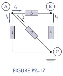
For the circuit in Figure P2—17:
- Identify the nodes and at least two loops.
- Identify any elements connected in series or parallel.
- Write KCL and KVL connection equations for the circuit.
Expert Solution & Answer
Want to see the full answer?
Check out a sample textbook solution
Students have asked these similar questions
How do you find the current that passes through the 1 Ohm resistor if there are two junctions? Do we have to use the Kirchoff's Junction Rule and/or is there another way?
A charger, a battery and a load are connected in parallel. The voltage across the charger is
12.5 volts and the battery has an emf of 12 volts and the internal resistance of 0.1 ohm. The
load of 2 ohms resistor. Find the current through the charger.
A 5-ohm resistance is connected in parallel with a 10-
ohm resistance. Another set, a 6-ohm and 8-ohm
resistances are also in parallel. The two sets are
connected in series.
-
-
-
Draw the circuit,
find the equivalent resistance,
total current, and
the voltage across each resistor.
Chapter 2 Solutions
ANALYSIS+DESIGN OF LINEAR CIRCUITS(LL)
Ch. 2 - Prob. 2.1PCh. 2 - The voltage across a particular resistor is 8.60 V...Ch. 2 - You can choose to connect either a 4.7-k resistor...Ch. 2 - A model railroader wants to be able to...Ch. 2 - A 100-k resistor dissipates 50mW. Find the current...Ch. 2 - The conductance of a particular semiconductor...Ch. 2 - In Figure P2—7 the resistor dissipates 25 mW. Find...Ch. 2 - In Figure P2—8 find Rx and the power supplied by...Ch. 2 - A resistor found in the lab has three orange...Ch. 2 - The iv characteristic of a nonlinear resistor is...
Ch. 2 - A 100-k resistor has a power rating of 0.25 W....Ch. 2 - A certain type of film resistor is available with...Ch. 2 - Figure P2—13 shows the circuit symbol for a class...Ch. 2 - A thermistor is a temperature-sensing element...Ch. 2 - In Figure P2-15i2=6A and i3=2A. Find i1 and i4.Ch. 2 - In Figure P2-16 determine which elements are in...Ch. 2 - For the circuit in Figure P2—17: Identify the...Ch. 2 - In Figure P2-17 i2=30mA and i4=20mA. Find i1 and...Ch. 2 - For the circuit in Figure P2—19: Identify the...Ch. 2 - In Figure P2-19 v2=20V,v3=20V, and v4=6V. Find...Ch. 2 - In many circuits the ground is often the metal...Ch. 2 - The circuit in figure P2-22 is organized around...Ch. 2 - Are any of the elements in Figure P2-23 in series...Ch. 2 - Are any of the elements in Figure P2-24 in series...Ch. 2 - Use the passive sign convention to assign voltage...Ch. 2 - If a wire is connected between nodes B and C in...Ch. 2 - The KCL equations for a three-node circuit are as...Ch. 2 - For the circuit in Figure P2—28, write a complete...Ch. 2 - For the circuit in Figure P2—29, write a complete...Ch. 2 - Find vx and ix in Figure P2-30. Compare the...Ch. 2 - A modeler wants to light his model building using...Ch. 2 - Find vx and ix in Figure P2-32.Ch. 2 - In Figure P2-33: Assign a voltage and current...Ch. 2 - Find vO in the circuit of Figure P2-34.Ch. 2 - Find the power provided by the source in Figure...Ch. 2 - Figure P2-36 shows a subcircuit connected to the...Ch. 2 - In Figure P2-37 ix=0.33mA. Find the value of R.Ch. 2 - Figure P2—38 shows a resistor with one terminal...Ch. 2 - Find the equivalent resistant REQ in Figure P2-39.Ch. 2 - Find the equivalent R EQ in Figure P2-40.Ch. 2 - Find the equivalent resistance REQ in Figure...Ch. 2 - Equivalent resistance is defined at a particular...Ch. 2 - Find REQ in Figure P2—43 when the switch is open....Ch. 2 - Find REQ between nodes A and B for each of the...Ch. 2 - Show how the circuit in Figure P2—45 could be...Ch. 2 - In Figure P2-46 find the equivalent resistance...Ch. 2 - In Figure P2-47 find the equivalent resistance...Ch. 2 - Select a value of RL in Figure P2-48 so that...Ch. 2 - Using no more than four 1-k resistors, show how...Ch. 2 - Do a source transformation at terminals A and B...Ch. 2 - For each of the circuits in Figure P2-51, find the...Ch. 2 - In Figure P2-52, the iv characteristic of network...Ch. 2 - Select the value of Rx in Figure P2-53 so that...Ch. 2 - Two 10-k potentiometers (a variable resistor whose...Ch. 2 - Select the value of R in Figure P2-55 so that...Ch. 2 - What is the range of REQ in Figure P2-56?Ch. 2 - Find the equivalent resistance between terminals A...Ch. 2 - Use voltage division in Figure P2-58 to find...Ch. 2 - Use voltage division in Figure P2-59 to obtain an...Ch. 2 - Use current division in Figure P2-60 to find...Ch. 2 - Use current division in Figure P2-61 to find an...Ch. 2 - Find ix,iy, and iz in Figure P2-62.Ch. 2 - Find vO in the circuit of Figure P2-63.Ch. 2 - You wish to drive a 1-k load from your car battery...Ch. 2 - Find the range of values of vo in Figure P2-65.Ch. 2 - Use current division in the circuit of Figure...Ch. 2 - Figure P2-67 shows a voltage bridge circuit, that...Ch. 2 - A Ideally, a voltmeter has infinite internal...Ch. 2 - Select values for R1,R2, and R3 in Figure P2-69 so...Ch. 2 - Select a value of Rx in Figure P2-70 so that...Ch. 2 - Select a value of Rx in Figure P2-71 so that...Ch. 2 - Use circuit reduction to find vx and ix in Figure...Ch. 2 - Use circuit reduction to find vx,ix, and px in...Ch. 2 - Use circuit reduction to find vx and ix in Figure...Ch. 2 - Use circuit reduction to find vx,ix, and px in...Ch. 2 - Use circuit reduction to find vx and ix in Figure...Ch. 2 - Use source transformation to find ix in Figure...Ch. 2 - Select a value for Rx so that ix=0A in Figure...Ch. 2 - Use source transformations in Figure P2-79 to...Ch. 2 - The current through RL in figure P2-80 is 100mA....Ch. 2 - Select Rx so that 50 V is across it in Figure...Ch. 2 - The box in the circuit in Figure P2-82 is a...Ch. 2 - A circuit is found to have the following element...Ch. 2 - Consider the circuit of Figure P2-88. Use MATLAB...Ch. 2 - Nonlinear Device Characteristics The circuit in...Ch. 2 - Prob. 2.92IPCh. 2 - Center Tapped Voltage Divider Figure P2-93 shows a...Ch. 2 - Active Transducer Figure P2-95 shows an active...Ch. 2 - Programmable Voltage Divider Figure P2-97 shows a...Ch. 2 - Analog Voltmeter Design Figure P2-98(a) shows a...Ch. 2 - MATLAB Function for Parallel Equivalent Resistors...
Knowledge Booster


Learn more about
Need a deep-dive on the concept behind this application? Look no further. Learn more about this topic, electrical-engineering and related others by exploring similar questions and additional content below.Similar questions
- Given four resistors R1 = 100 ohms, R2=250 ohms, R3 = 350 ohms, and R4 = 200 ohms such that R1 and R2 in parallel will be connected in series with R3 and R4 in parallel. The series-parallel combination is connected across a 24-volt DC power supply. Find the voltage across R2 and voltage across R4 voltage drops across R2 and R4 are both 12 V voltage drop across R2 is 18.63 V and voltage across R4 is 5.37 V voltage drop across R2 is 8.63 V and voltage across R4 is 15.37 V voltage drop across R2 is 8.63 V and voltage across R4 is 15.37 Varrow_forwardDETERMINE AND LABEL THE LOOPS. Solve the missing values of electric currents using Kirchhoff's laws. FInd the value of electric current flowing in and out of junction barrow_forwardWhich one or ones of the following statements about Kirchhoff's rules are correct? I) The junction rule is based on the law of conservation of energy. II) The loop rule is based on the law of conservation of energy. III) The number of required equations to find the unknown currents has to be as many as the number of all possible loops. O A) Il and II B) II O C) I and II O D) II O E) Iarrow_forward
- A charger , a battery and a load are connected in parallel. The voltage across the charger is 12.5 volts and the battery has an emf of 12 volts and internal resistance of 0.1 ohm. The load consists of a 2 ohms resistor. Find the current through the charger.arrow_forwardFor the circuit below, determine the resistor current. The source is 8 volts, the Zener potential is 5.2 volts and the resistor is 5k ohms.arrow_forwardFind the currents down through the load resistor in the circuitshown in the figure. Then convert the current source and the 2-Ohm resistor to an equivalent voltage source and again find theload current. Compare results.arrow_forward
- For the series-parallel arrangement shown in the Figure below, find (a) the supply current, (b) the current flowing through each resistor and (c) the p.d. across each resistor (d). power dissipated by each resistor.arrow_forwardfind the electrical power in the circuit in figure (2-40):- 3. 3.arrow_forwardI want Introducrion for ( MEASUREMENT USING DC BRIDGES ) by using Resistance Measurement using DC Bridges , Resistance Measurement using the Wheatstone Bridges and Resistance Measurement using the Kelvin Doubles Bridges ) please write the introduction in print font to copy it ?arrow_forward
- For the circuit below, determine the resistor voltage. The source is 5 volts, the Zener potential is 5.2 volts and the resistor is 1k ohms.arrow_forwardTrue/False: Consider connecting a Load Resistance across R2. Loading Effect is less when voltage across R2 'with load' is close to the Voltage 'without load' * Vin R2 V. out True O Falsearrow_forward4. Consider the following circuit. 3R SR 2R a) How many distinct currents flow in this circuit? The four loops shown are labeled A - D, and the junctions are labeled a - d. b) If we had to solve for these currents, how many independent equations would we need? c) Which loops and/or junctions would you choose, if you had to solve for the currents? (Many answers are possible here.) This diagram shows several different loops and junctions in the circuit. d) Set up a system of equations that would allow you to solve for the currents.arrow_forward
arrow_back_ios
SEE MORE QUESTIONS
arrow_forward_ios
Recommended textbooks for you
 Delmar's Standard Textbook Of ElectricityElectrical EngineeringISBN:9781337900348Author:Stephen L. HermanPublisher:Cengage Learning
Delmar's Standard Textbook Of Electricity
Electrical Engineering
ISBN:9781337900348
Author:Stephen L. Herman
Publisher:Cengage Learning
Kirchhoff's Rules of Electrical Circuits; Author: Flipping Physics;https://www.youtube.com/watch?v=d0O-KUKP4nM;License: Standard YouTube License, CC-BY