
ANALYSIS+DESIGN OF LINEAR CIRCUITS(LL)
8th Edition
ISBN: 9781119235385
Author: Thomas
Publisher: WILEY
expand_more
expand_more
format_list_bulleted
Concept explainers
Videos
Textbook Question
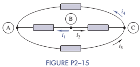
Chapter 2, Problem 2.15P
In Figure
Expert Solution & Answer
Want to see the full answer?
Check out a sample textbook solution
Students have asked these similar questions
Determine the total voltage, VT and the resistance, R3 in the circuit shown in Figureif the voltage across R1 is 4v and the current through R4 is 1.5 A.
A-2-1. Simplify the block diagram shown in Figure 2–17.
R(s)
+
H₁
G
H₂
(+
+
C(s)
The current flowing in resistor R in the circuit shown in figure is I2- I1.
See the Pic and Select one:
a) True
b) False
Chapter 2 Solutions
ANALYSIS+DESIGN OF LINEAR CIRCUITS(LL)
Ch. 2 - Prob. 2.1PCh. 2 - The voltage across a particular resistor is 8.60 V...Ch. 2 - You can choose to connect either a 4.7-k resistor...Ch. 2 - A model railroader wants to be able to...Ch. 2 - A 100-k resistor dissipates 50mW. Find the current...Ch. 2 - The conductance of a particular semiconductor...Ch. 2 - In Figure P2—7 the resistor dissipates 25 mW. Find...Ch. 2 - In Figure P2—8 find Rx and the power supplied by...Ch. 2 - A resistor found in the lab has three orange...Ch. 2 - The iv characteristic of a nonlinear resistor is...
Ch. 2 - A 100-k resistor has a power rating of 0.25 W....Ch. 2 - A certain type of film resistor is available with...Ch. 2 - Figure P2—13 shows the circuit symbol for a class...Ch. 2 - A thermistor is a temperature-sensing element...Ch. 2 - In Figure P2-15i2=6A and i3=2A. Find i1 and i4.Ch. 2 - In Figure P2-16 determine which elements are in...Ch. 2 - For the circuit in Figure P2—17: Identify the...Ch. 2 - In Figure P2-17 i2=30mA and i4=20mA. Find i1 and...Ch. 2 - For the circuit in Figure P2—19: Identify the...Ch. 2 - In Figure P2-19 v2=20V,v3=20V, and v4=6V. Find...Ch. 2 - In many circuits the ground is often the metal...Ch. 2 - The circuit in figure P2-22 is organized around...Ch. 2 - Are any of the elements in Figure P2-23 in series...Ch. 2 - Are any of the elements in Figure P2-24 in series...Ch. 2 - Use the passive sign convention to assign voltage...Ch. 2 - If a wire is connected between nodes B and C in...Ch. 2 - The KCL equations for a three-node circuit are as...Ch. 2 - For the circuit in Figure P2—28, write a complete...Ch. 2 - For the circuit in Figure P2—29, write a complete...Ch. 2 - Find vx and ix in Figure P2-30. Compare the...Ch. 2 - A modeler wants to light his model building using...Ch. 2 - Find vx and ix in Figure P2-32.Ch. 2 - In Figure P2-33: Assign a voltage and current...Ch. 2 - Find vO in the circuit of Figure P2-34.Ch. 2 - Find the power provided by the source in Figure...Ch. 2 - Figure P2-36 shows a subcircuit connected to the...Ch. 2 - In Figure P2-37 ix=0.33mA. Find the value of R.Ch. 2 - Figure P2—38 shows a resistor with one terminal...Ch. 2 - Find the equivalent resistant REQ in Figure P2-39.Ch. 2 - Find the equivalent R EQ in Figure P2-40.Ch. 2 - Find the equivalent resistance REQ in Figure...Ch. 2 - Equivalent resistance is defined at a particular...Ch. 2 - Find REQ in Figure P2—43 when the switch is open....Ch. 2 - Find REQ between nodes A and B for each of the...Ch. 2 - Show how the circuit in Figure P2—45 could be...Ch. 2 - In Figure P2-46 find the equivalent resistance...Ch. 2 - In Figure P2-47 find the equivalent resistance...Ch. 2 - Select a value of RL in Figure P2-48 so that...Ch. 2 - Using no more than four 1-k resistors, show how...Ch. 2 - Do a source transformation at terminals A and B...Ch. 2 - For each of the circuits in Figure P2-51, find the...Ch. 2 - In Figure P2-52, the iv characteristic of network...Ch. 2 - Select the value of Rx in Figure P2-53 so that...Ch. 2 - Two 10-k potentiometers (a variable resistor whose...Ch. 2 - Select the value of R in Figure P2-55 so that...Ch. 2 - What is the range of REQ in Figure P2-56?Ch. 2 - Find the equivalent resistance between terminals A...Ch. 2 - Use voltage division in Figure P2-58 to find...Ch. 2 - Use voltage division in Figure P2-59 to obtain an...Ch. 2 - Use current division in Figure P2-60 to find...Ch. 2 - Use current division in Figure P2-61 to find an...Ch. 2 - Find ix,iy, and iz in Figure P2-62.Ch. 2 - Find vO in the circuit of Figure P2-63.Ch. 2 - You wish to drive a 1-k load from your car battery...Ch. 2 - Find the range of values of vo in Figure P2-65.Ch. 2 - Use current division in the circuit of Figure...Ch. 2 - Figure P2-67 shows a voltage bridge circuit, that...Ch. 2 - A Ideally, a voltmeter has infinite internal...Ch. 2 - Select values for R1,R2, and R3 in Figure P2-69 so...Ch. 2 - Select a value of Rx in Figure P2-70 so that...Ch. 2 - Select a value of Rx in Figure P2-71 so that...Ch. 2 - Use circuit reduction to find vx and ix in Figure...Ch. 2 - Use circuit reduction to find vx,ix, and px in...Ch. 2 - Use circuit reduction to find vx and ix in Figure...Ch. 2 - Use circuit reduction to find vx,ix, and px in...Ch. 2 - Use circuit reduction to find vx and ix in Figure...Ch. 2 - Use source transformation to find ix in Figure...Ch. 2 - Select a value for Rx so that ix=0A in Figure...Ch. 2 - Use source transformations in Figure P2-79 to...Ch. 2 - The current through RL in figure P2-80 is 100mA....Ch. 2 - Select Rx so that 50 V is across it in Figure...Ch. 2 - The box in the circuit in Figure P2-82 is a...Ch. 2 - A circuit is found to have the following element...Ch. 2 - Consider the circuit of Figure P2-88. Use MATLAB...Ch. 2 - Nonlinear Device Characteristics The circuit in...Ch. 2 - Prob. 2.92IPCh. 2 - Center Tapped Voltage Divider Figure P2-93 shows a...Ch. 2 - Active Transducer Figure P2-95 shows an active...Ch. 2 - Programmable Voltage Divider Figure P2-97 shows a...Ch. 2 - Analog Voltmeter Design Figure P2-98(a) shows a...Ch. 2 - MATLAB Function for Parallel Equivalent Resistors...
Knowledge Booster


Learn more about
Need a deep-dive on the concept behind this application? Look no further. Learn more about this topic, electrical-engineering and related others by exploring similar questions and additional content below.Similar questions
- Consider the circuit shown in the figure below. Given that R2/R1 = 2, the current passing through the second resistor will grow with a char- acteristic time constant given by L R1 R2 L (A) 2² R1 L (B) 2R1 2L R1 (D) R1 L (E) R1arrow_forwardSolve it clearly please P2= - 9 Q2= - 0.5 P3= - 2 Q3= - 0.6arrow_forwardFor R1=55, R2=D125, R33D135, R4=15, R5=40, R63D90 and V1=4 V in the shown figure, use circuit reduction and current/voltage division rules to calculate the following: R6 R1 R5 R3 R2 V1 V2 R4 V13= V2=arrow_forward
- Reduce the block diagram shown in Figure (1) by using the reduction rules G5 H₂ C(s) "00000000" H₂ G₁ Figure (1) H₂arrow_forwardSince R1=9282.13ohm, R2=3403.87ohm and Ri=Infinite in the circuit given in the figure, write the equivalent resistance in Ohms between the terminals A-B.arrow_forwardFinding the direction of the currents. Finding currents given that R2: 10.94 x 10^2 ohmR3: 9.89 x 10^2 ohmR4: 25 ohm Terminal Potential: Battery 1: 5 V using Kirchoff's laws. You will check some of the laws that govern electrical circuitsDirect current: conservation of current in a node, addition of potentialsfor series components, addition of currents for parallel componentsarrow_forward
- SS 2-31 Find REQ in Figure P2-31 when the switch is open. Repeat when the switch is closed. 100 Ω Μ σα REQ 50 Ω 100 Ω 100 Ωarrow_forwardTwo batteries are connected in parallel delivering power to a power resistor. The first battery has an open circuit voltage of 12.6 V and an internal resistance of 0.2 ohm. The second battery has an open circuit voltage of 12.2 V and an internal resistance of 0.3 ohm. Find the maximum power delivered to the load resistance.arrow_forwardfind the value of V1 and i2, mat lab simulation showed v1 to be 148.9v and i2 to be 129.3A but those numbers are not exactarrow_forward
- Find the potential difference between point a and point b for the situation shown below. Here ₁ = 12.0 V, E₂ = 8.77 V and R₁ = 4.13, R₂ = 5.44 , and R3 = 2.28 0. Va - Vb = R₂ V R3 R₁ Warrow_forwardConsider the circuit shown in below Figure, Find values of the resistances R1 and R2 that cause the voltages v1 and v2 to be v1 = 1 V and v2 = 2 V. 500 2 + + R1 R2 () 5 mA 3 mA V1 V2 6:03 PM 50°F Clear 2/18/2022 P Type here to search Del End F10 PgUp. F11 PgDn F12 PrtScn Home F7 F2 F3 F1 & ) Backspace %23 %24 % 4. 5 7 8. 9. 2 3 W.arrow_forwardA student wants to measure the electric potential difference across the resistor R2 for the circuit below. R, D A R2 Where should a student hook up a voltmeter to measure the electric potential difference across resistor R2? From point B to point D From point A to point D From point B to point C From point A to point Carrow_forward
arrow_back_ios
SEE MORE QUESTIONS
arrow_forward_ios
Recommended textbooks for you
 Introductory Circuit Analysis (13th Edition)Electrical EngineeringISBN:9780133923605Author:Robert L. BoylestadPublisher:PEARSON
 Delmar's Standard Textbook Of ElectricityElectrical EngineeringISBN:9781337900348Author:Stephen L. HermanPublisher:Cengage Learning
 Programmable Logic ControllersElectrical EngineeringISBN:9780073373843Author:Frank D. PetruzellaPublisher:McGraw-Hill Education
 Fundamentals of Electric CircuitsElectrical EngineeringISBN:9780078028229Author:Charles K Alexander, Matthew SadikuPublisher:McGraw-Hill Education
 Electric Circuits. (11th Edition)Electrical EngineeringISBN:9780134746968Author:James W. Nilsson, Susan RiedelPublisher:PEARSON
 Engineering ElectromagneticsElectrical EngineeringISBN:9780078028151Author:Hayt, William H. (william Hart), Jr, BUCK, John A.Publisher:Mcgraw-hill Education,
Introductory Circuit Analysis (13th Edition)
Electrical Engineering
ISBN:9780133923605
Author:Robert L. Boylestad
Publisher:PEARSON
Delmar's Standard Textbook Of Electricity
Electrical Engineering
ISBN:9781337900348
Author:Stephen L. Herman
Publisher:Cengage Learning
Programmable Logic Controllers
Electrical Engineering
ISBN:9780073373843
Author:Frank D. Petruzella
Publisher:McGraw-Hill Education
Fundamentals of Electric Circuits
Electrical Engineering
ISBN:9780078028229
Author:Charles K Alexander, Matthew Sadiku
Publisher:McGraw-Hill Education
Electric Circuits. (11th Edition)
Electrical Engineering
ISBN:9780134746968
Author:James W. Nilsson, Susan Riedel
Publisher:PEARSON
Engineering Electromagnetics
Electrical Engineering
ISBN:9780078028151
Author:Hayt, William H. (william Hart), Jr, BUCK, John A.
Publisher:Mcgraw-hill Education,
Nodal Analysis for Circuits Explained; Author: Engineer4Free;https://www.youtube.com/watch?v=f-sbANgw4fo;License: Standard Youtube License