
Concept explainers
Videos
(a)
The couple
Answer to Problem 18.77P
The couple
Explanation of Solution
Given information:
The total mass is
Write the expression for the sum of the moment acting on the body along x -direction.
Here, the product of the moment of the inertia of
Write the expression for the sum of the moment acting on the body along y -direction.
Write the expression for the sum of the moment acting on the body along z -direction.
Here, the moment of the inertia along the z -direction is
Draw the diagram for the for the sheet metal component.
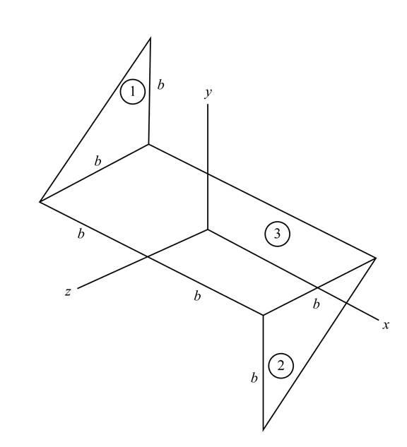
Figure-(1)
Write the expression for the area of the section 1 shown in the Figure-(1).
Here, the constant dimension is
Write the expression for the area of the section 2 shown in the Figure-(1).
Write the expression for the area of the section 3 shown in the Figure-(1).
Write the expression for the total area of the sheet.
Substitute
Write the expression of mass per unit area of the system.
Here, the mass of the sheet metal component is
Write the expression for the variation of the
Here, the coordinate of the considered point is
The below figure represent the schematic diagram of the elemental strip of section 1.
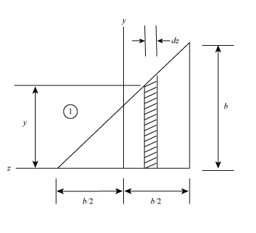
Figure-(2)
Write the expression for the distance of the centroid of the element from the
Write the expression for the mass of the elemental strip.
Here, the area of the elemental strip is
Write the expression for the moment of inertia of the element with respect to z- axis.
Write the expression for the moment of the inertia of the section 1.
Write the expression for the product of moment of inertia of the plane
Write the expression for the product of moment of inertia of the plane
Write the expression for the variation of the
The below figure represent the schematic diagram of the elemental strip of section 2.
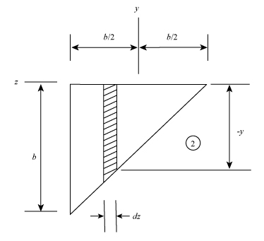
Figure-(3)
Write the expression for the mass of the elemental strip of section 2.
Write the expression for the moment of the inertia of the section 2.
Write the expression for the product of moment of inertia of the plane
Write the expression for the product of moment of inertia of the plane
Write the expression of mass per unit area of the section3 in Figure-(1).
Here, the mass of the rectangular sheet metal component is
Write the expression for the moment of the inertia of the section 3.
The product moment of the inertia for the plane
Write the expression for the moment of the inertia of the whole system.
Write the expression for the product of moment of inertia of the whole system.
Write the expression for the product of moment of inertia of the whole system.
Draw the diagram for the system to shows the action of forces on the system.
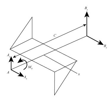
Figure-(4)
Here, the reaction on the point
Calculation:
Substitute
Substitute
Substitute
Substitute
Substitute
Substitute
Substitute
Substitute
Substitute
Conclusion:
The couple
(b)
The dynamic reactions at
The dynamic reactions at
Answer to Problem 18.77P
The dynamic reactions at
The dynamic reactions at
Explanation of Solution
Write the expression for the dynamic reaction at point
Write the expression for the dynamic reaction at point
Write the expression for the reaction forces along the y- direction.
Write the expression for the reaction forces along the x- direction.
Write the expression for the sum of the moment acting on the body along x -direction.
Here, distance between the point
Write the expression for the sum of the moment acting on the body along y -direction.
Calculation:
Substitute
Substitute
Substitute
Substitute
Substitute
Substitute
Substitute
Substitute
Substitute
Substitute
Substitute
Substitute
Substitute
Substitute
Conclusion:
The dynamic reactions at
The dynamic reactions at
Want to see more full solutions like this?
Chapter 18 Solutions
Vector Mechanics For Engineers


- 2. A cord is wrapped around a homogeneous disk of radius r = 0.5 m and mass m = 14. 25 kg. If the cord is pulled upward with a force T of magnitude 171 N, determine a. the acceleration of the center of the disk, b. the angular acceleration of the disk, c. the acceleration of the cord. T 0.5 m Go A Draw the Free Body Diagram.arrow_forwardThe parallelogram linkage shown moves in the vertical plane with the uniform 9.3-kg bar EF attached to the plate at E by a pin which is welded both to the plate and to the bar. A torque (not shown) is applied to link AB through its lower pin to drive the links in a clockwise direction. When e reaches 51°, the links have an angular acceleration and an angular velocity of 7.0 rad/s² and 2.3 rad/s, respectively. For this instant calculate the magnitudes of the force F and torque M supported by the pin at E. Welded 1435 mm pin F 995 995 mm mm B D Horizontal Answers: F = i N M = i N•marrow_forward3. The connecting rod of the steam engine shown schematically is assumed to be a slender uniform rod. 4 ft long weighing 322 Ib. the crank AO is 1ft long and rotates at a constant rate of 10 rad/s. the force on the 64.4 Ib cross-head at the given instant is 2142 Ib. neglecting friction. Determine the normal force on the crosshead and the horizontal and vertical components at crank pin force at A. А 45deg Вarrow_forward
- The uniform 2-kg slender bar AB is mounted on a vertical shaft at C.A constant couple of 9 N-m is applied to the bar. Calculate the angular acceleration of the bar and the magnitude of the horizontal reaction at C at the instant when the angular velocity of the bar is 6 rad/s.arrow_forward6. The uniform ring of mass m = 10 kg and radius r= 0.5 m is hinged at O and can rotate freely in the vertical plane. If the ring is released with a clockwise angular velocity o = 4 rad/s from the position shown where OC is horizontal, determine the magnitude of the reaction at pin O the instant the disk is released. toarrow_forwardGear A has a mass of 1 kg and a radius of gyration of 30 mm; gear B has a mass of 4 kg and a radius of gyration of 75 mm; gear C has a mass of 9 kg and a radius of gyration of 100 mm. The system is at rest when a couple M0 of constant magnitude 4 N.m is applied to gear C . Assuming that no slipping occurs between the gears, determine the number of revolutions required for disk A to reach an angular velocity of 300 rpm.arrow_forward
- Question #1. A The 5 kg paper roll has a radius of gyration about its centre of k= 90 mm. The coefficient of kinetic friction between the wall and the roll at C is µk=0.20. A friction couple of 4 Nm acts on the roll at A as it turns when the force F-50 N is applied. Determine (a) the angular acceleration of the roll B (b) the force in the link AB 300 mm 125 mmarrow_forwardProblem (1) Gears A and B each have a mass of 4 kg and a radius of gyration of 75 mm about their centers, while gear C has a mass of 15 kg and a radius of gyration of 180 mm about its center. A couple moment M = (0.20) N-m is applied to gear C. Determine the number of revolutions gears A and B experience if gear C increases its angular velocity from 25 rpm to 500 rpm. B 80 mm S0 mm 200 mmarrow_forwardA ring of mass m =1 kg and radius R = 1m is attached to a vertical shaft by means of a frictionless pin. Coordinates xyz are fixed to the ring as shown and the frictionless pin at A is aligned with the x-axis. The vertical shaft precesses about the Z-axis with constant angular velocity 2 = 1 rad/s. (a) At a particular moment when 0 = 30° and = 4 rad/s, find the value of Ö . This comes from a sum of the moments about the x-axis. Do not neglect gravity. (b) Find the torque or moment necessary that must be applied about the vertical shaft in order to keep it turning at a constant rate of N = 1 rad/s. Ring R XG A 1 Ixx = lyy =mR? G Iz = mR?arrow_forward
- The 10-lb disk P (?o = 0) was placed in contact with the wall at C and with disk Q weighing 8-lb. Disk Q maintains an angular acceleration equal to 2 rad/s2,CCW and has a couple moment of M= 31 lb-ft, CCW. If the coefficient of kinetic friction at contact surfaces is 0.25, determine the initial angular acceleration of disk P. Also, determine the reactions at points A and B. reminder: Neglect the weight of rod AB CCW- COUNTERCLOCKWISE SHOW FULL SOLUTION!!!!arrow_forwardConsider a steel plate of mass m with dimensions L and w that is equally supported by two ball bearings (one on each end of the shaft shown at pointa A and B). At the instant shown below, the plate is released from rest. Part A: Determine an expression for the plate's angular acceleration magnitude a at this in- stant. (Hint: Use Euler's 2nd Law for pinned rotation and the parallel axis theorem.) Part B: Show that the magnitude of the reaction force at each bearing at this instant is R = mg/8. (Hint: Use the kinematics to relate the acceleration of the center of mass G to the angular acceleration. Use Euler's 1st Law to find the reaction forces with the acceleration you determined. As viewed from the side there are two forces acting on the system weight and two reaction forces both pointing upward at the same location.) A foye مر B L २arrow_forwardThe 24-kg roll of paper has a radius of gyration KA = 90 mm about an axis passing through point A. It is pin supported at both ends by two brackets AB. The roll rests against a wall for which the coefficient of kinetic friction is = 0.2 and a vertical force F = 27 Nis applied to the end of the paper. (Figure 1) Figure 300 mm 125 mm 1 of 1 ▼ Part A Determine the angular acceleration of the roll as the paper unrolls. Express your answer using three significant figures. Enter positive value if the angular acceleration is clockwise and negative value if the angular acceleration is counterclockwise. IVE ΑΣΦΑ ↓↑ vec α = Submit Provide Feedback Request Answer ? rad/s² Next >arrow_forward
 Elements Of ElectromagneticsMechanical EngineeringISBN:9780190698614Author:Sadiku, Matthew N. O.Publisher:Oxford University Press
 Mechanics of Materials (10th Edition)Mechanical EngineeringISBN:9780134319650Author:Russell C. HibbelerPublisher:PEARSON
 Thermodynamics: An Engineering ApproachMechanical EngineeringISBN:9781259822674Author:Yunus A. Cengel Dr., Michael A. BolesPublisher:McGraw-Hill Education
 Control Systems EngineeringMechanical EngineeringISBN:9781118170519Author:Norman S. NisePublisher:WILEY
 Mechanics of Materials (MindTap Course List)Mechanical EngineeringISBN:9781337093347Author:Barry J. Goodno, James M. GerePublisher:Cengage Learning
 Engineering Mechanics: StaticsMechanical EngineeringISBN:9781118807330Author:James L. Meriam, L. G. Kraige, J. N. BoltonPublisher:WILEY