
Elements Of Electromagnetics
7th Edition
ISBN: 9780190698614
Author: Sadiku, Matthew N. O.
Publisher: Oxford University Press
expand_more
expand_more
format_list_bulleted
Related questions
Concept explainers
Question

Transcribed Image Text:**Educational Text on Angular Dynamics**
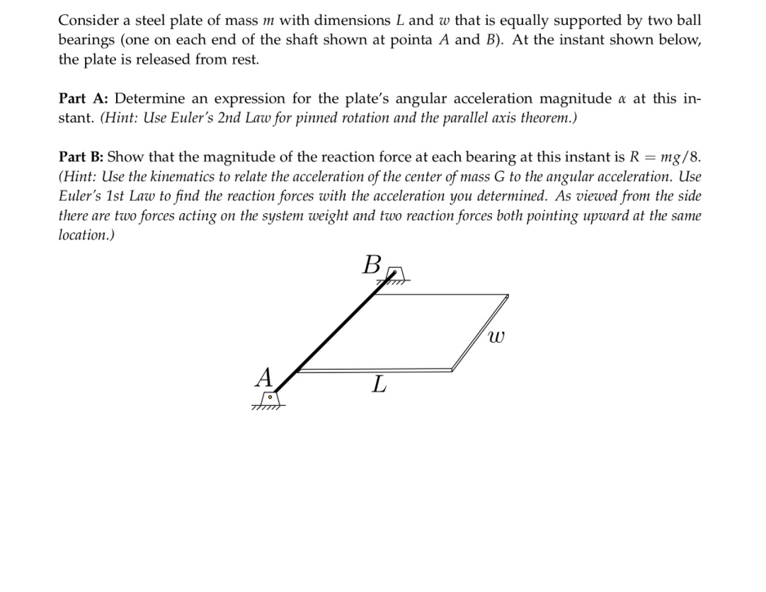
Consider a scenario involving a steel plate with mass \( m \) and dimensions \( L \) and \( w \). This plate is equally supported by two ball bearings situated at points \( A \) and \( B \). At the specified moment depicted, the plate is released from rest.
**Part A: Analysis of Angular Acceleration**
- **Objective:** Determine the expression for the angular acceleration magnitude \( \alpha \) of the plate at this instant.
- **Methodology:** Utilize Euler's Second Law for pinned rotation combined with the parallel axis theorem to derive the necessary expression.
**Part B: Reaction Force Calculation**
- **Objective:** Validate that the magnitude of the reaction force at each bearing is \( R = \frac{mg}{8} \).
- **Methodology:**
- Apply kinematics to connect the acceleration of the center of mass \( G \) with the angular acceleration.
- Use Euler’s First Law to calculate the reaction forces based on the angular acceleration obtained.
- Consider that, from a side view, the system is influenced by the weight and two upward-acting reaction forces at the same location.
**Diagram Explanation:**
- The diagram illustrates a rectangular plate resting horizontally, supported by two bearings at points \( A \) and \( B \). The distance between these points is denoted as \( L \). The gravitational force (\( mg \)) acts downwards through the center of mass, while the bearings provide upward reaction forces.
In summary, this exercise involves applying fundamental principles of rotational dynamics to solve for angular acceleration and reaction forces acting on a rigid body.
Expert Solution
This question has been solved!
Explore an expertly crafted, step-by-step solution for a thorough understanding of key concepts.

This is a popular solution

Trending nowThis is a popular solution!

Step by stepSolved in 3 steps with 5 images

Follow-up Questions
Read through expert solutions to related follow-up questions below.
Follow-up Question
have you figured out part b yet?
Solution
by Bartleby Expert
Follow-up Question
has part B of this problem been done
Solution
by Bartleby Expert
Follow-up Questions
Read through expert solutions to related follow-up questions below.
Follow-up Question
have you figured out part b yet?
Solution
by Bartleby Expert
Follow-up Question
has part B of this problem been done
Solution
by Bartleby Expert
Knowledge Booster


Learn more about
Need a deep-dive on the concept behind this application? Look no further. Learn more about this topic, mechanical-engineering and related others by exploring similar questions and additional content below.Similar questions
- Wheels A and B are uniform 16.1-lb cylinders with frictionless axles as shown. A 32.2-lb box C with a center of mass at G is supported on the axles. Calculate the acceleration of the box if the wheels roll without slipping.arrow_forwardQ6. The unbalanced wheel, as shown in Figure Q6 below, has a mass of 30 kg acting through its mass centre G and a radius of gyration kg = 0.15 m. It rolls without slipping on the horizontal surface, When the mass centre G passes the horizontal line through O as shown, the angular velocity of the wheel is 2 rads¹. For this instant, (a) (b) (c) (d) identify the type of motion of the wheel, draw the free body, kinematic and kinetic diagrams of the wheel clearly showing all the operating forces and moments, develop all the relevant kinetic and kinematics relationships to a global axes system of your choice, and determine the angular acceleration a of the wheel, the normal force N and friction force F acting on the wheel at its point of contact with the horizontal surface. 01 m 0.25 marrow_forwardThe 35 lb slender rod AB is 277 in. long and at rest in a horizontal position supported by a spring located at h = 226 in. from the suspension cable at B. If the cable at B fails, answer the following 1) Part A: Determine the magnitude of the acceleration of end A. 2) Part B: Determine the magnitude of the acceleration of end B. 3) Part C: Determine the angular acceleration of the rod.arrow_forward
- The 24-kg roll of paper has a radius of gyration KA = 90 mm about an axis passing through point A. It is pin supported at both ends by two brackets AB. The roll rests against a wall for which the coefficient of kinetic friction is = 0.2 and a vertical force F = 27 Nis applied to the end of the paper. (Figure 1) Figure 300 mm 125 mm 1 of 1 ▼ Part A Determine the angular acceleration of the roll as the paper unrolls. Express your answer using three significant figures. Enter positive value if the angular acceleration is clockwise and negative value if the angular acceleration is counterclockwise. IVE ΑΣΦΑ ↓↑ vec α = Submit Provide Feedback Request Answer ? rad/s² Next >arrow_forwardProblem 4. A thin, semi-circular ring of mass m and radius R is pinned to ground at point O. The bar is released from rest in the position shown. Note that a = 2R, IG = mR² - ma² (a) Find the mass moment of inertia of the body about point O (b) Find the angular acceleration of the ring when released (c) Find the reaction forces on the ring at point O Ans: (b) a=0.5(g/R); (c) Ox = (mga)/(2R), Oy = mg/2 6.0 g G a -R-arrow_forwardConsider the wheel shown below with radius R, mass m, and radius of gyration ko¹ The wheel rolls without slipping under the action of a clockwise torque M. At the instant shown the spring with spring constant ks is unstretched. Derive an expression for the velocity of the wheel center of mass G after the center of mass has moved a distance d. (Hint: Use rigid body work-energy principles. The work done to the system by the applied moment is McA0 and A0 can be related to the distace d by the no-slip condition.) Us G R M м, ко ////arrow_forward
arrow_back_ios
arrow_forward_ios
Recommended textbooks for you
- Elements Of ElectromagneticsMechanical EngineeringISBN:9780190698614Author:Sadiku, Matthew N. O.Publisher:Oxford University Press
 Mechanics of Materials (10th Edition)Mechanical EngineeringISBN:9780134319650Author:Russell C. HibbelerPublisher:PEARSON
 Thermodynamics: An Engineering ApproachMechanical EngineeringISBN:9781259822674Author:Yunus A. Cengel Dr., Michael A. BolesPublisher:McGraw-Hill Education
  Control Systems EngineeringMechanical EngineeringISBN:9781118170519Author:Norman S. NisePublisher:WILEY
 Mechanics of Materials (MindTap Course List)Mechanical EngineeringISBN:9781337093347Author:Barry J. Goodno, James M. GerePublisher:Cengage Learning
 Engineering Mechanics: StaticsMechanical EngineeringISBN:9781118807330Author:James L. Meriam, L. G. Kraige, J. N. BoltonPublisher:WILEY
Elements Of Electromagnetics
Mechanical Engineering
ISBN:9780190698614
Author:Sadiku, Matthew N. O.
Publisher:Oxford University Press
Mechanics of Materials (10th Edition)
Mechanical Engineering
ISBN:9780134319650
Author:Russell C. Hibbeler
Publisher:PEARSON
Thermodynamics: An Engineering Approach
Mechanical Engineering
ISBN:9781259822674
Author:Yunus A. Cengel Dr., Michael A. Boles
Publisher:McGraw-Hill Education
Control Systems Engineering
Mechanical Engineering
ISBN:9781118170519
Author:Norman S. Nise
Publisher:WILEY
Mechanics of Materials (MindTap Course List)
Mechanical Engineering
ISBN:9781337093347
Author:Barry J. Goodno, James M. Gere
Publisher:Cengage Learning
Engineering Mechanics: Statics
Mechanical Engineering
ISBN:9781118807330
Author:James L. Meriam, L. G. Kraige, J. N. Bolton
Publisher:WILEY