
Electronics Fundamentals: Circuits, Devices & Applications
8th Edition
ISBN: 9780135072950
Author: Thomas L. Floyd, David Buchla
Publisher: Prentice Hall
expand_more
expand_more
format_list_bulleted
Videos
Textbook Question
Chapter 18, Problem 23P
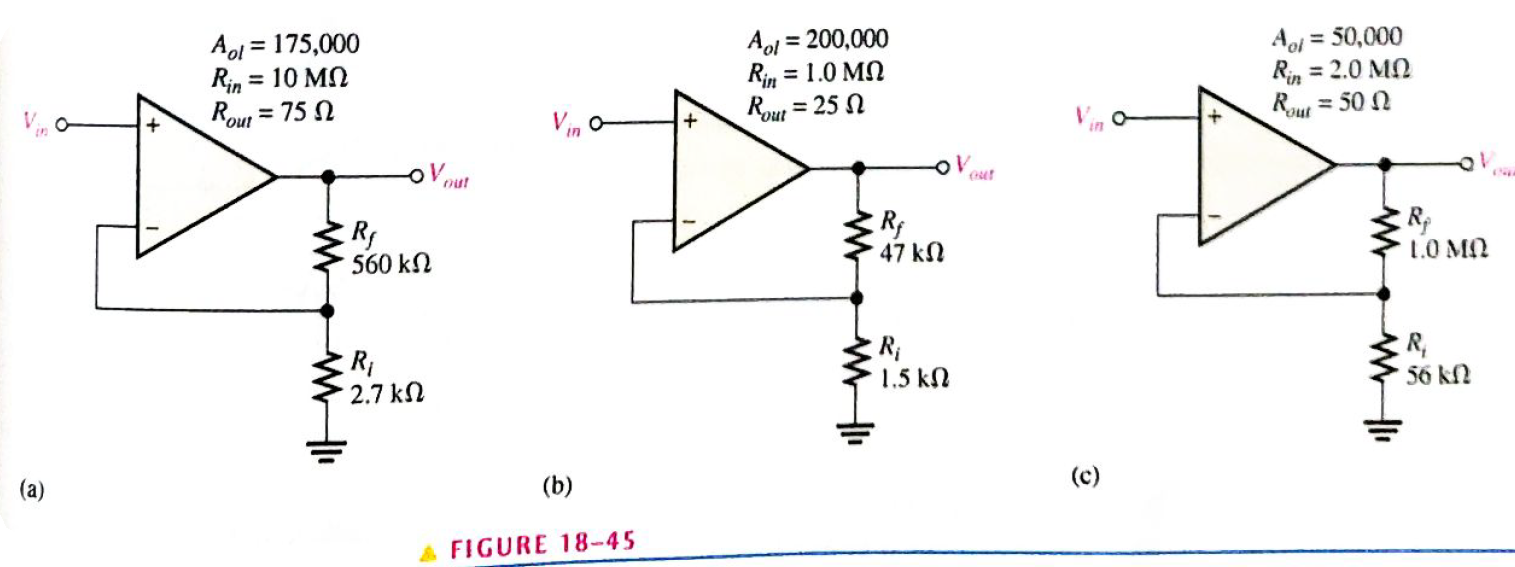
Determine the input and output resistances for each amplifier configuration in Figure 18-45.
Expert Solution & Answer
Want to see the full answer?
Check out a sample textbook solution
Students have asked these similar questions
Please show all work for parts A,B, and C at the bottom of the Op-Amp.
What is value of output voltage (vo).
Determine the type of opamp circuit, the gain and the output voltage of the circuit for each of the operational amp circuits below
Chapter 18 Solutions
Electronics Fundamentals: Circuits, Devices & Applications
Ch. 18 - When a diff-amp has identical signals on both...Ch. 18 - A high CMRR for a diff-amp means the common-mode...Ch. 18 - Prob. 3TFQCh. 18 - The open-loop voltage gain of an op-amp is also...Ch. 18 - Prob. 5TFQCh. 18 - Prob. 6TFQCh. 18 - In a voltage-follower, the open-loop and...Ch. 18 - Prob. 8TFQCh. 18 - Prob. 9TFQCh. 18 - If the feedback resistor in an amplifier is open,...
Ch. 18 - Which characteristic docs not necessarily apply to...Ch. 18 - In selecting an op-amp. suppose you have several...Ch. 18 - Prob. 3STCh. 18 - Prob. 4STCh. 18 - Prob. 5STCh. 18 - Prob. 6STCh. 18 - Prob. 7STCh. 18 - Prob. 8STCh. 18 - If you know an op-amp's open-loop gain and nothing...Ch. 18 - Prob. 10STCh. 18 - Prob. 11STCh. 18 - The highest possible input resistance is achieved...Ch. 18 - Compare a practical op-amp to an ideal op-amp.Ch. 18 - Two IC op-amps are available to you. Their...Ch. 18 - Identify the type of input and output...Ch. 18 - Prob. 4PCh. 18 - A certain diff-amp has a differential gain of 60...Ch. 18 - A certain diff-amp has a CMRR of 65 dB. If the...Ch. 18 - Identify the type of input mode for each op-amp in...Ch. 18 - Show the common-mode input in Figure 18-37 in an...Ch. 18 - Determine the bias current, IBIAS, given that the...Ch. 18 - Distinguish between input bias current and input...Ch. 18 - A certain op-amp has a CMRR of 250,000. Convert...Ch. 18 - The open-loop gain of a certain op-amp is 175,000....Ch. 18 - The op-amp data sheet specifies a CMRR of 300,000...Ch. 18 - Figure 18-38 shows the output voltage of an op-amp...Ch. 18 - How long does it take the output voltage of an...Ch. 18 - Identify each of the op-amp configurations in...Ch. 18 - For the amplifier in Figure 18-40. determine the...Ch. 18 - Determine the closed-loop gain of each amplifier...Ch. 18 - Find the value of Rf that will produce the...Ch. 18 - Find the gain of each in amplifier in Figure...Ch. 18 - If a signal voltage of 10 mV applied to each...Ch. 18 - Determine the approximate values for each of the...Ch. 18 - Determine the input and output resistances for...Ch. 18 - Repeat Problem 23 for each circuit in Figure...Ch. 18 - Repeat Problem 23 for each circuit in Figure...Ch. 18 - Prob. 26PCh. 18 - Prob. 28PCh. 18 - Prob. 29PCh. 18 - Prob. 30PCh. 18 - Prob. 31PCh. 18 - Prob. 32P
Knowledge Booster


Learn more about
Need a deep-dive on the concept behind this application? Look no further. Learn more about this topic, electrical-engineering and related others by exploring similar questions and additional content below.Similar questions
- close loop gainsarrow_forwardCalculate the total offset voltage for the circuit shown below for op-amp specification values of input offset values, VIO=2.8 mV and IIO=110 nA with RF=14000 ohm and Rin= 3000 ohm.arrow_forwardExplain any two methods of reducing interference and what type of feedback has been used in an emitter followerarrow_forward
- Drive the following equation Vo=-11 Vin. Using summing amplifier RI circuit.arrow_forwardYou are tasked to look for a converter circuit design that has the specifications tabulated in Table I. The aim is to produce an output voltage of 20 V which can be used to drive a load of 120 W. The converter must operate in CCM. Table I: Design Specifications Values 35 V Design Parameters Input voltage Switching frequency Output current ripple Output voltage ripple 60 kHz 5 % 1 % a) Sketch the final converter and label all parameter valuesarrow_forwardClamper circuit: Vi (p-p)= 10 volt (Sinewave) F-1 kHz R= 10 Kohm V= 4 volt C- I micro F Find and analysis of and Sketch the output signal for the clamper circuit.arrow_forward
- EQUATION OF OUTPUT VOLTAGE( NEED ONLY HANDWRITTEN SOLUTION PLEASE OTHERWISE DOWNVOTE).arrow_forwardA single phase fully controlled bridge converter supplies a load drawing constant and ripple free load current, if the triggering angle is 30°, the input power factor will bearrow_forwardCalculate the total offset voltage for the circuit shown below for op-amp specification values of input offset values, VIO=3.5 mV and IIO=73 nA with RF=20000 ohm and Rin=3000 ohm.arrow_forward
arrow_back_ios
SEE MORE QUESTIONS
arrow_forward_ios
Recommended textbooks for you
 Electricity for Refrigeration, Heating, and Air C...Mechanical EngineeringISBN:9781337399128Author:Russell E. SmithPublisher:Cengage Learning
Electricity for Refrigeration, Heating, and Air C...
Mechanical Engineering
ISBN:9781337399128
Author:Russell E. Smith
Publisher:Cengage Learning
Current feedback amplifiers - Overview and compensation techniques; Author: Texas Instruments;https://www.youtube.com/watch?v=2WZotqHiaq8;License: Standard Youtube License