
Introductory Circuit Analysis (13th Edition)
13th Edition
ISBN: 9780133923605
Author: Robert L. Boylestad
Publisher: PEARSON
expand_more
expand_more
format_list_bulleted
Related questions
Concept explainers
Question
close loop gains
![**Understanding Noninverting Operational Amplifier Configurations**
An operational amplifier connected in a noninverting configuration has an open-loop gain (AOL) of 105. The resistors are specified as R2 = 495 kΩ and R1 = 5 kΩ. The task is to determine both the actual and ideal gain of the amplifier.
**Concepts to Explore:**
1. **Operational Amplifier (Op-Amp):**
- An electronic device used to amplify voltage.
- Configurations include inverting and noninverting.
2. **Noninverting Amplifier Configuration:**
- Provides a positive voltage gain.
- The input signal is applied to the non-inverting (+) terminal.
3. **Open-Loop Gain (AOL):**
- The gain of the amplifier without any feedback.
- In this scenario, AOL = 105.
4. **Closed-Loop Gain:**
- Gain when feedback is applied.
- In a noninverting amplifier:
\[
\text{Gain} = 1 + \frac{R2}{R1}
\]
- Calculations:
\[
\text{Ideal Gain} = 1 + \frac{495\, k\Omega}{5\, k\Omega} = 1 + 99 = 100
\]
- Assuming high open-loop gain, actual gain approximates the ideal gain.
**Practical Application:**
- When implementing this circuit, the actual gain can vary slightly due to the finite open-loop gain and real-world component tolerances.
- Useful in applications requiring precise voltage amplification without phase inversion.
Understanding this configuration aids in designing amplifiers for audio equipment, signal processing, and other electronic applications.](https://content.bartleby.com/qna-images/question/2bf0a2b4-4cef-40fd-b09b-f8efed4785e6/d9447402-4eab-474d-a722-3898046ea33c/zrczhve_processed.png)

Transcribed Image Text:**Understanding Noninverting Operational Amplifier Configurations**
An operational amplifier connected in a noninverting configuration has an open-loop gain (AOL) of 105. The resistors are specified as R2 = 495 kΩ and R1 = 5 kΩ. The task is to determine both the actual and ideal gain of the amplifier.
**Concepts to Explore:**
1. **Operational Amplifier (Op-Amp):**
- An electronic device used to amplify voltage.
- Configurations include inverting and noninverting.
2. **Noninverting Amplifier Configuration:**
- Provides a positive voltage gain.
- The input signal is applied to the non-inverting (+) terminal.
3. **Open-Loop Gain (AOL):**
- The gain of the amplifier without any feedback.
- In this scenario, AOL = 105.
4. **Closed-Loop Gain:**
- Gain when feedback is applied.
- In a noninverting amplifier:
\[
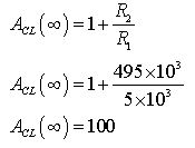
\text{Gain} = 1 + \frac{R2}{R1}
\]
- Calculations:
\[
\text{Ideal Gain} = 1 + \frac{495\, k\Omega}{5\, k\Omega} = 1 + 99 = 100
\]
- Assuming high open-loop gain, actual gain approximates the ideal gain.
**Practical Application:**
- When implementing this circuit, the actual gain can vary slightly due to the finite open-loop gain and real-world component tolerances.
- Useful in applications requiring precise voltage amplification without phase inversion.
Understanding this configuration aids in designing amplifiers for audio equipment, signal processing, and other electronic applications.
Expert Solution
arrow_forward
Step 1
The infinite close loop gain for the non-inverting op-amp is given as:

Step by stepSolved in 2 steps with 2 images

Knowledge Booster


Learn more about
Need a deep-dive on the concept behind this application? Look no further. Learn more about this topic, electrical-engineering and related others by exploring similar questions and additional content below.Similar questions
Recommended textbooks for you
- Introductory Circuit Analysis (13th Edition)Electrical EngineeringISBN:9780133923605Author:Robert L. BoylestadPublisher:PEARSON
 Delmar's Standard Textbook Of ElectricityElectrical EngineeringISBN:9781337900348Author:Stephen L. HermanPublisher:Cengage Learning
 Programmable Logic ControllersElectrical EngineeringISBN:9780073373843Author:Frank D. PetruzellaPublisher:McGraw-Hill Education
  Fundamentals of Electric CircuitsElectrical EngineeringISBN:9780078028229Author:Charles K Alexander, Matthew SadikuPublisher:McGraw-Hill Education
 Electric Circuits. (11th Edition)Electrical EngineeringISBN:9780134746968Author:James W. Nilsson, Susan RiedelPublisher:PEARSON
 Engineering ElectromagneticsElectrical EngineeringISBN:9780078028151Author:Hayt, William H. (william Hart), Jr, BUCK, John A.Publisher:Mcgraw-hill Education,
Introductory Circuit Analysis (13th Edition)
Electrical Engineering
ISBN:9780133923605
Author:Robert L. Boylestad
Publisher:PEARSON
Delmar's Standard Textbook Of Electricity
Electrical Engineering
ISBN:9781337900348
Author:Stephen L. Herman
Publisher:Cengage Learning
Programmable Logic Controllers
Electrical Engineering
ISBN:9780073373843
Author:Frank D. Petruzella
Publisher:McGraw-Hill Education
Fundamentals of Electric Circuits
Electrical Engineering
ISBN:9780078028229
Author:Charles K Alexander, Matthew Sadiku
Publisher:McGraw-Hill Education
Electric Circuits. (11th Edition)
Electrical Engineering
ISBN:9780134746968
Author:James W. Nilsson, Susan Riedel
Publisher:PEARSON
Engineering Electromagnetics
Electrical Engineering
ISBN:9780078028151
Author:Hayt, William H. (william Hart), Jr, BUCK, John A.
Publisher:Mcgraw-hill Education,