
Videos
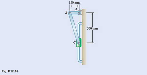
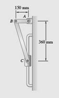
The uniform rods AB and BC are of mass 3 kg and 8 kg, respectively, and collar C has a mass of 4 kg. Knowing that at the instant shown the velocity of collar C is 0.9 m/s downward, determine the velocity of point B after rod AB has rotated through 90°.
The velocity of point B after rod AB has rotated through 90°.
Answer to Problem 17.45P
Velocity of point B after
Explanation of Solution
Given information:
Mass of rod AB,
Mass of rod BC,
Mass of collar C,
Velocity of collar,
Concept used:
Energy conservation principle
Calculation:
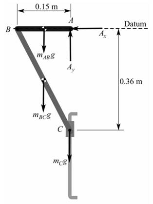
(a)Initial Position
Moment of inertial of rod BC,
Moment of inertial of rod AB,
Initial kinetic energy,
We know from the figure that,
Initial Potential energy,
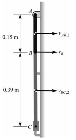
(b) Final Position
Now, rod AB is rotated through
Final kinetic energy,
From the figure,
Final potential energy,
Using energy conservation principle,
Conclusion:
Therefore, the velocity of point B when rod AB rotates through
Want to see more full solutions like this?
Chapter 17 Solutions
Vector Mechanics For Engineers


- The 200-mm-radius disk rolls without sliding on the surface shown. Knowing that the distance BG is 160 mm and that at the instant shown the disk has an angular velocity of 9.2 rad/s counterclockwise and an angular acceleration of 2.6 rad/s² clockwise, determine the acceleration of A. 800 mm The acceleration of A is 200 mm B 1 m/s² →.arrow_forwardA 1-m-long uniform slender bar AB has an angular velocity of 12 rad/s and its center of gravity has a velocity of 2 m/s as shown. About which point is the angular momentum of A smallest at this instant? P1 P2 P3 P4 It is the same about all the points.arrow_forwardThe 200-mm-radius disk rolls without sliding on the surface shown. Knowing that the distance BG is 160 mm and that at the instant shown the disk has an angular velocity of 8.6 rad/s counterclockwise and an angular acceleration of 2.3 rad/s2 clockwise, determine the acceleration of A. 800 mm The acceleration of A is 11.55 200 mm B m/s²_arrow_forward
- Gear B has an angular acceleration of aß = 0.15t² rad/s², where t is in seconds, and an initial angular velocity of wB = 0.3 rad/s. The radius of Gear A is 2.75 cm and the radius of Gear B is 2 cm. Gears A and B are pinned and the centers of the pins are at points C and D respectively. (i) Solve for the angular velocity and angular acceleration of Gear A after Gear B has a revolution or 3π. (ii) Solve for the velocity and acceleration vectors where the two gears come in contact at point P. Hint: You need to select which gear you are solving the acceleration vector. UIC Gear A MIE Шв, ав 2.75 cm 2cm Gear Barrow_forwardCollars A and B are attached by a rod of length 30 cm, as shown below. The joint at A is a ball-and-socket and at B a pin joint. Collar A moves in the z direction, while the guide bar for collar B is on xy plane.At the instant shown,collar A is at a height of 24cm and collar B is moving with a speed of 3 m/s towards the x axis. Find the (a) angular velocity of the rod, and (b) the sliding of collarB.arrow_forwardShow that knowing that at the instant shown, step AB of the step exerciser is rotating counterclockwise at a constant rate O.arrow_forward
- Q4. The three bars AB, BC, and CD form a mechanism as shown. Points A and D are at rest with respect to the ground. Bar AB has a clockwise angular rate of 12 rad/s as shown and anti-clockwise angular acceleration 2 rad/s?. Determine the angular velocity and angular acceleration of bar BC. B 350 mm 200 mm `12 rad/s 300 mm 350 mmarrow_forwardDetermine the rate of change H, of the angular momentum HD of the rod CDE, assuming that at the instant considered the assembly has an angular velocity o = (12 rad/s)i and an angular acceleration a = -(96 rad/s?)i. C A D В Z. 9 in. E 9 in. 3 in. 3 in.arrow_forward(6) The spring-loaded plunger F has a velocity of 3 m/s in the direction indicated. A roller at corner E of the equilateral triangular member BDE contacts the smooth surface of the plunger. The roller at corner D of member BDE slides freely along the horizontal slot. Member AB is pin connected to member BDE at point B. Determine the angular velocities of members BDE and AB and the velocity of roller D for the instant shown using the Method of Instantaneous Center of Zero Velocity. D E F 45° B. 75 cm A 30 83 cmarrow_forward
- (6) The spring-loaded plunger F has a velocity of 3 m/s in the direction indicated. A roller at corner E of the equilateral triangular member BDE contacts the smooth surface of the plunger. The roller at corner D of member BDE slides freely along the horizontal slot. Member AB is pin connected to member BDE at point B. Determine the angular velocities of members BDE and AB and the velocity of roller D for the instant shown using the Method of Instantaneous Center of Zero Velocity. 83cm 45° 75 cm 30arrow_forwardThe mechanism below has a crank that revolves clockwise at point O at a speed of 2000 rpm. B 1.2 kg 200 mm 60 mm 30° 0 Using vector diagrams, determine: a. The linear velocity of the piston and the angular velocity of the link AB about A. b. The angular acceleration of the link AB about A and the inertial resistance produced by the piston. c. Using trigonometry, confirm your results for the velocity in parts (i), explain your reasons behind which method is preferable, and identify the error margin for your velocity answers.arrow_forwardThe shown disk rolls on the plane surface with a constant counterclockwise angular velocity of 10 rad / s. Bar AB slides on the surface of the disk at A, determine: a) Coriolis acceleration, sense and magnitudearrow_forward
 Elements Of ElectromagneticsMechanical EngineeringISBN:9780190698614Author:Sadiku, Matthew N. O.Publisher:Oxford University Press
 Mechanics of Materials (10th Edition)Mechanical EngineeringISBN:9780134319650Author:Russell C. HibbelerPublisher:PEARSON
 Thermodynamics: An Engineering ApproachMechanical EngineeringISBN:9781259822674Author:Yunus A. Cengel Dr., Michael A. BolesPublisher:McGraw-Hill Education
 Control Systems EngineeringMechanical EngineeringISBN:9781118170519Author:Norman S. NisePublisher:WILEY
 Mechanics of Materials (MindTap Course List)Mechanical EngineeringISBN:9781337093347Author:Barry J. Goodno, James M. GerePublisher:Cengage Learning
 Engineering Mechanics: StaticsMechanical EngineeringISBN:9781118807330Author:James L. Meriam, L. G. Kraige, J. N. BoltonPublisher:WILEY