Concept explainers
Videos
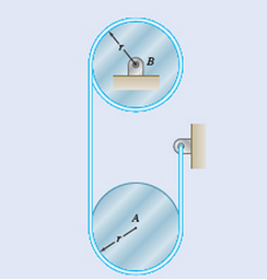
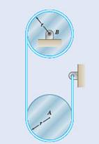
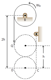
Two uniform cylinders, each of weight
(a)
Calculate the distance by which cylinder A is raised before the angular velocity of cylinder B is reduced to
Answer to Problem 17.32P
Cylinder A will be raised by
Explanation of Solution
Given:
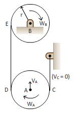
Both the cylinders are connected by the belt as shown in the figure.
Weight of cylinders
Radius of cylinders
Angular velocity of the cylinder
Concept used:
Work and energy principle.
Calculation:
Kinetic energy,
At position 1:
At position 2:
Work is done,
h is the rise of the cylinder.
Applying principle of work and energy,
Conclusion:
Thus, the cylinder will raise by
(b)
Calculate the tension in belt where two cylinders are connected.
Answer to Problem 17.32P
Tension in the belt connecting two cylinders is
Explanation of Solution
Given:
Weight of cylinders
Radius of cylinders
Angular velocity of cylinder,
Concept used:
Work and energy conservation principle
Calculation:
We have,
D moves twice the distance than A.
Distance = 2h
Let the tension in cord be Q.
Hence, work done
As per the work and energy principle,
Conclusion:
In this way, by using work and energy principle we can calculate the tension in belt adjoining two cylinders.
Want to see more full solutions like this?
Chapter 17 Solutions
Vector Mechanics for Engineers: Dynamics


- D C Answer: B 0.4 m- 0.4 m Two identical slender rods AB and BC are welded together to form an L-shaped assembly. The assembly is pressed against a spring at D and released from the position shown. Knowing that the maximum angle of rotation of the assembly in its subsequent motion is 58° with the horizontal (counterclockwise), determine the magnitude of the angular velocity of the assembly as it passes through the position where rod AB forms an angle of 27° with the horizontal.arrow_forwardQ3. Two identical slender rods AB and BC are welded together to form an L-shaped assembly. The assembly is pressed against a spring at D and released from the position shown. Knowing that the maximum angle of rotation of the assembly in its subsequent motion is 90° counterclockwise, determine the magnitude of the angular velocity of the assembly as it passes through the position where rod AB forms an angle of 30° with the horizontal. h D B 1 0.4 m 0.4 marrow_forward4. Each of the gears A and B has a mass of 2.4 kg and a radius of gyration of 60 mm, while gear C has a mass of 12 kg and a radius of gyration of 150 mm. A couple M of constant magnitude 10 Nm is applied to gear C. Determine (a) the number of revolutions of gear C required for its angular velocity to increase from 100 to 450 rpm, (b) the corresponding tangential force acting on gear A. В S0 mm, S0 mm 200 mm. Marrow_forward
- The blade of a portable saw and the rotor of its motor have a total weight of 2.5 lb and a combined radius of gyration of 1.5 in. Knowing that the blade rotates as shown at the rate w1= 1500 rpm, determine the magnitude and direction of the couple M that a worker must exert on the handle of the saw to rotate it with a constant angular velocity w2= -(2.4 rad/s)j.arrow_forwardEach of the gears A and B has a mass of 2.4 kg and a radius of gyration of 60 mm, while gear C has a mass of 12 kg and a radius of gyration of 150 mm. A couple M of constant magnitude 10 N.m is applied to gear C determine a ) the number of revolutions of gear C required for its angular velocity to increase from 100 to 450 rpm, (b) the corresponding tangential force acting on gear A.arrow_forwardA 6-lb homogeneous disk of radius 3 in. spins as shown at the constant rate w1 = 60 rad/s. The disk is supported by the fork-ended rod AB , which is welded to the vertical shaft CBD The system is at rest when a couple M0 is applied as shown to the shaft for 3 s and then removed. Knowing that the maximum angular velocity reached by the shaft is 18 rad/s, determine (a) the couple M0) the dynamic reactions at C and D after the couple has been removed.arrow_forward
- The gear train shown consists of four gears of the same thickness and of the same material; two gears are of radius r, and the other two are of radius nr. The system is at rest when the couple M0 is applied to shaft C. Denoting by I0 the moment of inertia of a gear of radius r, determine the angular velocity of shaft A if the couple M0 is applied for one revolution of shaft C.arrow_forwardTwo uniform rods AB and CE, each of weight 3 lb and length 2 ft, are welded to each other at their midpoints. Knowing that this assembly has an angular velocity of constant magnitude w = 12 rad/s, determine the magnitude and direction of the angular momentum HD of the assembly about D.arrow_forwardA 9-kg uniform disk is attached to the 5-kg slender rod AB by means of frictionless pins at B and C. The assembly rotates in a vertical plane under the combined effect of gravity and of a couple M that is applied to rod AB. Knowing that at the instant shown the assembly has an angular velocity of 6 rad/s and an angular acceleration of 25 rad/s2 , both counterclockwise, determine (a) the couple M, (b) the force exerted by pin C on member ABarrow_forward
- In the gear arrangement shown, gears A and C are attached to rod ABC, that is free to rotate about B, while the inner gear B is fixed. Knowing that the system is at rest, determine the magnitude of the couple M that must be applied to rod ABC, if 2.5 s later the angular velocity of the rod is to be 240 rpm clockwise. Gears A and C ABC weighs 4 lb.arrow_forwardA 2.5-kg homogeneous disk of radius 80 mm rotates at the constant rate ω1 = 50 rad/s with respect to arm ABC, which is welded to a shaft DCE. Knowing that at the instant shown, shaft DCE has an angular velocity w2 = (12 rad/s)k and an angular acceleration a2= = (8 rad/s2)k, determine (a) the couple that must be applied to shaft DCE to produce that acceleration, (b) the corresponding dynamic reactions at D and E.arrow_forward4. The link EF of mass 2 kg is welded at point A to a link ABC of mass 2 kg, which rotates about a pivot B. A spring of constant k =300 N/m and of un-stretched length 150 mm is attached to the link ABC as shown. Knowing that in the position shown the assembly has an angular velocity of 10 rad/s clockwise, (a) Determine the angular velocity when the assembly has rotated 90° clockwise, (b) Find the corresponding angular acceleration of part (a), and (c) Find the corresponding reaction force at point B. (For (b) and (c), set up all the required equations with a Free-Body-Diagram 150 mm and a Kinetic Diagram) 150 mm, 150 mm, E 150 mm 360 mmarrow_forward
 Elements Of ElectromagneticsMechanical EngineeringISBN:9780190698614Author:Sadiku, Matthew N. O.Publisher:Oxford University Press
 Mechanics of Materials (10th Edition)Mechanical EngineeringISBN:9780134319650Author:Russell C. HibbelerPublisher:PEARSON
 Thermodynamics: An Engineering ApproachMechanical EngineeringISBN:9781259822674Author:Yunus A. Cengel Dr., Michael A. BolesPublisher:McGraw-Hill Education
 Control Systems EngineeringMechanical EngineeringISBN:9781118170519Author:Norman S. NisePublisher:WILEY
 Mechanics of Materials (MindTap Course List)Mechanical EngineeringISBN:9781337093347Author:Barry J. Goodno, James M. GerePublisher:Cengage Learning
 Engineering Mechanics: StaticsMechanical EngineeringISBN:9781118807330Author:James L. Meriam, L. G. Kraige, J. N. BoltonPublisher:WILEY