
Concept explainers
Videos
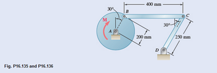
The 6-kg rod BC connects a 10-kg disk centered at A to a 5-kg rod CD. The motion of the system is controlled by the couple M applied to disk A. Knowing that at the instant shown disk A has an angular velocity of 36 rad/s clockwise and an angular acceleration of 150 rad/s2 counterclockwise determine (a) the couple M, (b) the components of the force exerted at C on rod BC.
(a)
The couple M applied at disk A.
Answer to Problem 16.136P
The couple M applied at disk A,
Explanation of Solution
Given information:
Radius of disk A, rAB=200mm.
Rod BC mass, m = 6kg.
Disk mass, m = 10kg.
Rod CD mass, m = 5kg.
Angular velocity of disk A,
Angular acceleration of the disk A,
A diagram is given with all dimensions,
Velocity of disk AB,
Disk radius,
Disk angular velocity,
Since point C velocity is parallel to point B velocity, the point C velocity magnitude and direction is same as point B
Rod CD angular velocity
Disk B acceleration,
Rod BC acceleration tangential component,
Rod BC acceleration,
Rod CD acceleration tangential component,
Rod CD acceleration,
Equation forces horizontal component from equations A and B,
Equation forces vertical component from equations A and B,
Acceleration of point A is zero since it is pivoted
Rod BC acceleration of mass centre P,
Rod CD acceleration of mass centre Q,
Disk AB effective force at mass centre,
Disk AB moment of inertia,
Rod BC effective force at mass centre,
Rod BC moment of inertia,
Rod CD effective force at mass centre,
Rod CD moment of inertia,
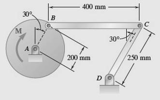
Rod BC free body diagram
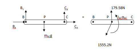
Figure A
Moment at point B from above figure,
Rod CD free body diagram
Figure B
Moment at point D from above figure,
Combined disk AB and rod BC free body diagram
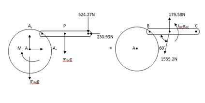
Figure C
From above figure, take moment at point A,
M is couple applied at point A
At disk A, couple applied magnitude is
Conclusion:
At disk A, couple applied magnitude is
(b)
Find the force components exerted on rod BC
Answer to Problem 16.136P
The force horizontal component exerted at point C is
Explanation of Solution
Given information:
Rod BC mass, m = 6kg
Disk mass, m = 10kg
Rod CD mass, m = 5kg
Rod BC free body diagram

Figure A
Moment at point B from above figure,
Rod CD free body diagram

Figure B
Moment at point D from above figure,
Conclusion:
The force horizontal component exerted at point C is
Want to see more full solutions like this?
Chapter 16 Solutions
Vector Mechanics For Engineers


- Three shafts and four gears are used to form a gear train which will transmit 7.5 kW from the motor at A to a machine tool at F. (Bearings for the shafts are omitted from the sketch.) Knowing that the frequency of the motor is 30 Hz, determine the magnitude of the couple that is applied to shaft (a) AB(b) CD (c) EF.arrow_forwardEach of the gears A and B has a mass of 2.4 kg and a radius of gyration of 60 mm, while gear C has a mass of 12 kg and a radius of gyration of 150 mm. A couple M of constant magnitude 10 N.m is applied to gear C determine a ) the number of revolutions of gear C required for its angular velocity to increase from 100 to 450 rpm, (b) the corresponding tangential force acting on gear A.arrow_forwardTwo identical 4-lb slender rods AB and BC are connected by a pin at B and by the cord AC. The assembly rotates in a vertical plane under the combined effect of gravity and a 6-lb·ft couple M applied to rod AB. Knowing that in the position shown the angular velocity of the assembly is zero, determine (a) the angular acceleration of the assembly, (b) the tension in cord AC.arrow_forward
- Required information NOTE: This is a multi-part question. Once an answer is submitted, you will be unable to return to this part. A 4-kg slender rod is welded to the edge of a 3-kg uniform disk as shown. The assembly rotates about A in a vertical plane under the combined effect of gravity and of the vertical force P. Know that at the instant shown, the assembly has an angular velocity of 12 rad/s and an angular acceleration of 36.5 rad/s2, both counterclockwise. 120 mm Determine the force P. B The force P is D 240 mm с 240 mm (You must provide an answer before moving on to the next part.) |N.↓arrow_forwardGreek engineers had the unenviable task of moving large columns from the quarries to the city. One engineer, Chersiphron, tried several different techniques to do this. One method was to cut pivot holes into the ends of the stone and then use oxen to pull the column. The 4-ft diameter column weighs 12,000 lbs, and the team of oxen generates a constant pull force of 1500 lbs on the center of the cylinder G. Knowing that the column starts from rest and rolls without slipping, determine (a) the velocity of its center G after it has moved 5 ft, (b) the minimum static coefficient of friction that will keep it from slipping.arrow_forwardTwo disks of the same material are attached to a shaft as shown. Disk A has a radius r and a thickness 2b, while disk B has a radius nr and a thickness 2b. A couple M with a constant magnitude is applied when the system is at rest and is removed after the system has executed two revolutions. Determine the value of n that results in the largest final speed for a point on the rim of disk B.arrow_forward
- escribe the motion of bodies A and Bof each mechanism shown as: (1) tre n about a fixed axis; or (3) general plane motion A B (b) (c)arrow_forwardThe 10-in.-radius brake drum is attached to a larger flywheel which is not shown. The total mass moment of inertia of the flywheel and drum is 22 lb ⋅ ft ⋅ s 2 and the coefficient of kinetic friction between the drum and the brake shoe is 0.41. Knowing that the initial angular velocity is 255 rpm clockwise, determine the force which must be exerted by the hydraulic cylinder at point B if the system is to stop in 85 revolutions. DO NOT ROUND OFF IN THE SOLUTION. ROUND OFF ONLY THE FINAL ANSWERarrow_forwardTwo uniform cylinders, each of mass m = 6 kg and radius r = 125 mm, are connected by a belt as shown. Knowing that at the instant shown the angular velocity of cylinder A is 30 rad/s counterclockwise, determine (a) the time required for the angular velocity of cylinder A to be reduced to 5 rad/s, (b) the tension in the portion of belt connecting the two cylinders.arrow_forward
- 4. Each of the gears A and B has a mass of 2.4 kg and a radius of gyration of 60 mm, while gear C has a mass of 12 kg and a radius of gyration of 150 mm. A couple M of constant magnitude 10 Nm is applied to gear C. Determine (a) the number of revolutions of gear C required for its angular velocity to increase from 100 to 450 rpm, (b) the corresponding tangential force acting on gear A. В S0 mm, S0 mm 200 mm. Marrow_forwardQ3. Two identical slender rods AB and BC are welded together to form an L-shaped assembly. The assembly is pressed against a spring at D and released from the position shown. Knowing that the maximum angle of rotation of the assembly in its subsequent motion is 90° counterclockwise, determine the magnitude of the angular velocity of the assembly as it passes through the position where rod AB forms an angle of 30° with the horizontal. h D B 1 0.4 m 0.4 marrow_forwardThe steel roll shown has a mass of 1200 kg, has a centroidal radius of gyration of 150 mm, and is lifted by two cables looped around its shaft. Knowing that at the instant shown the acceleration of the roll is 150 mm/s2 downward and that for each cable TA = 3000 N, determine (a) the corresponding tension TB, (b) the angular acceleration of the roll.arrow_forward
 Elements Of ElectromagneticsMechanical EngineeringISBN:9780190698614Author:Sadiku, Matthew N. O.Publisher:Oxford University Press
 Mechanics of Materials (10th Edition)Mechanical EngineeringISBN:9780134319650Author:Russell C. HibbelerPublisher:PEARSON
 Thermodynamics: An Engineering ApproachMechanical EngineeringISBN:9781259822674Author:Yunus A. Cengel Dr., Michael A. BolesPublisher:McGraw-Hill Education
 Control Systems EngineeringMechanical EngineeringISBN:9781118170519Author:Norman S. NisePublisher:WILEY
 Mechanics of Materials (MindTap Course List)Mechanical EngineeringISBN:9781337093347Author:Barry J. Goodno, James M. GerePublisher:Cengage Learning
 Engineering Mechanics: StaticsMechanical EngineeringISBN:9781118807330Author:James L. Meriam, L. G. Kraige, J. N. BoltonPublisher:WILEY