Concept explainers
Videos
(a)
The angular acceleration of the gear
Answer to Problem 16.36P
The angular acceleration of the gear
Explanation of Solution
Given Information:
The mass of the gear
Write the expression for the tangential acceleration of the gear teeth.
Here, the angular acceleration is
Write the expression for the tangential acceleration of the gear
Here, the angular acceleration of gear
Write the expression for the tangential acceleration of the gear
Here, the angular acceleration of gear
Write the expression for the tangential acceleration of the gear
Here, the angular acceleration of gear
Draw the free body diagram for the gear
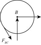
Figure-(1)
Draw the kinetic diagram of the gear
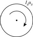
Figure-(2)
Write the expression for the moment of inertia gear
Here, the mass of the gear
Write the expression for the external moment at
Here, the tangential force exerted by gear
Write the expression for the effective forces using the Figure-(2).
Since, the system of external forces is equivalent to system of effective forces hence
Substitute
Draw the free body diagram for the gear
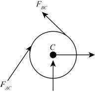
Figure-(3)
Draw the kinetic diagram for the gear
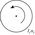
Figure-(4)
Write the expression for the moment of inertia gear
Here, the mass of the gear is
Write the expression for the external moment at
Here, the tangential force exerted by gear
Write the expression for the effective forces using the Figure-(4).
Since, the system of external forces is equivalent to system of effective forces hence
Substitute
Draw the free body diagram for the gear
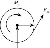
Figure-(5)
Draw the kinetic diagram of the gear
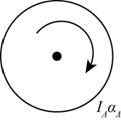
Figure-(6) Write the expression for the moment of inertia gear
Here, the mass of the gear is
Write the expression for the external moment at
Here, the couple force applied on the gear
Write the expression for the effective forces using the Figure-(6).
Since, the system of external forces is equivalent to system of effective forces hence
Substitute
Calculation:
Substitute
Substitute
Substitute
The tangential acceleration of the gear
Substitute
The tangential acceleration of the gear
Substitute
Substitute
Substitute
Substitute
Substitute
Substitute
Substitute
Substitute
Substitute
Conclusion:
The angular acceleration of the gear
(b)
The tangential force exerted by gear
Answer to Problem 16.36P
The tangential force exerted by gear
Explanation of Solution
Write the expression for the tangential force exerted by gear
Calculation:
Substitute
Conclusion:
The tangential force exerted by gear
Want to see more full solutions like this?
Chapter 16 Solutions
Vector Mechanics for Engineers: Dynamics


- Which of the systems are equivalent to the couple in (a)?arrow_forwardThe uniform rod AB of weight W is supported by the two inclined planes. Neglecting friction, determine of the couple C that keeps the bar at rest in the position shown.arrow_forward3. The connecting rod of the steam engine shown schematically is assumed to be a slender uniform rod. 4 ft long weighing 322 Ib. the crank AO is 1ft long and rotates at a constant rate of 10 rad/s. the force on the 64.4 Ib cross-head at the given instant is 2142 Ib. neglecting friction. Determine the normal force on the crosshead and the horizontal and vertical components at crank pin force at A. А 45deg Вarrow_forward
- 3. As part of a test, the two aircraft engines are revved up and the propeller pitches are adjusted so as to result in the fore and aft thrusts shown. What force F must be exerted by the ground on each of the main braked wheels at A and B to counteract the turning effect of the two propeller thrusts? Neglect any ef- fects of the nose wheel C, which is turned 90° and unbraked. 500 lb 8 14' C 500 lb Ans. F = 875 lbarrow_forwardDetermine the magnitude and direction of the couple moment actingon the gear shown.arrow_forwardA loading car is at rest on a track forming an angle of25owith the vertical. The gross weight of the car andits load is 5500 lb, and it acts at a point 30 in. from the track, halfway between the two axles. The car is heldby a cable 24 in. from the track. Determine the tensionin the cable and the reaction ateach pair of wheels.arrow_forward
- 4. (20 pts) A concrete block is lifted by a hoisting mechanism in which the cables are securely wrapped around their respective drums. The drums are fastened together and rotate as a single unit at their center of mass O. Combined mass of drum is 150 kg, and radius of gyration at O is 450 mm. A constant tension of 1.8 kN is maintained in the cable by the power unit at A. Determine the vertical acceleration of the block and the resultant force on the bearing at O. 600 mm 300 mm P = 1.8 kN m = 150 kg ko = 450 mm %3D 45° 300 kgarrow_forwardA uniform disk of mass m = 4 kg and radius r = 150 mm is supported by a belt ABCD that is bolted to the disk at B and C. If the belt suddenly breaks at a point located between A and B, draw the FBD and KD for the disk immediately after the break.arrow_forwardTwo disks of the same material are attached to a shaft as shown. Disk A has a radius r and a thickness 2b, while disk B has a radius nr and a thickness 2b. A couple M with a constant magnitude is applied when the system is at rest and is removed after the system has executed two revolutions. Determine the value of n that results in the largest final speed for a point on the rim of disk B.arrow_forward
- The 48-lb load is removed and a 288-lb in. clockwise couple is applied successively at .A. D and E. Determine the components of the reactions at B and F if the couple is applied (a) at A. (b) at D, (c) at E.arrow_forward2. Two 20-kg uniform bars are connected to form the linkage shown. Neglecting the effect of friction, determine the reaction at D immediately after the linkage is released from rest in the position shown. 600 mm A B 300 mm -300 mmarrow_forwardBar BC weighs 161 lb and has a radius of gyration of mass with respect to a hor- izontal axis through G of 3.0 ft. The bar is supported by the cords AB and CD which rotate in the same vertical plane. The speed of the mass centre, when in the position shown, is 12 fps. Determine the tension in cables AB and CD for this position.arrow_forward
 International Edition---engineering Mechanics: St...Mechanical EngineeringISBN:9781305501607Author:Andrew Pytel And Jaan KiusalaasPublisher:CENGAGE L