
Fundamentals of Geotechnical Engineering (MindTap Course List)
5th Edition
ISBN: 9781305635180
Author: Braja M. Das, Nagaratnam Sivakugan
Publisher: Cengage Learning
expand_more
expand_more
format_list_bulleted
Concept explainers
Videos
Textbook Question
Chapter 16, Problem 16.10P
An eccentrically loaded foundation is shown in Figure 16.25. Use FS of 4 and determine the maximum allowable load that the foundation can carry. Use Meyerhof’s effective area method.
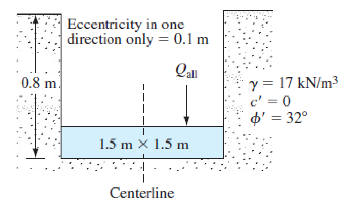
FIG. 16.25
Expert Solution & Answer

Trending nowThis is a popular solution!

Students have asked these similar questions
An eccentrically loaded continuous foundation is shown in Figure P4.11. Determine the ultimate load Qu per unit length that the foundation can carry. Use the reduction factor method [Eq. (4.63)].
Question 01.
Using the Fadum chart provided, calculate the total vertical stress due to 200 kPa uniform contact pressure at a depth of 6m below point A for the rectangular raft foundation as per Question 1 part of the attached image.
L1 = 7m
L2 = 3m
B1 = 9m
B2 = 4m
Question 02.
A section of the proposed foundation in Question 01 has an obstruction. A redesign is carried out as shown in Question 2 part of the attached image. The original proposed footprint was maintained, and the section removed from the design has a width of B3 = 2mCalculate the total vertical stress at the same depth below A and the same uniform pressure in Question 01.
2 ft
2 ft
24 ft
24 ft
24 ft
Problem 4
B
D
E
F
G
| 3 ft
DL=100 kip DL=180 kip
LL = 60 kịp LL = 120 kip
DL=190 kip
DL=110 ki
• The plan of a mat foundation with column loads is shown in
Figure 2. Use the rigid method to calculate the soil
pressures at point A, B, C, D, E, F, G, H, , J, K, L, M and N. The
size of the mat is 76 ft x 96 ft, all columns are 24 in x 24 in
in section, and qlnet = 1.5 kip/ft². Verify that the soil
pressures are less than the net allowable bearing capacity.
LL = 120 kip LL = 70 ki
30 ft
DL=180 kip
DL=400 kip DL=200 kip
LL = 250 kip LL = 120 kip
DL=360 kip
LL = 120 kip LL = 200 kip
ex
30 ft
DL-190 kip DL=500 kip
LL = 130'kip LL = 240 kip
DL=T10 kip DL=200 kip
LL =300 kip LL =120 kip
30 ft
DL=180 kip DL=120 kip
LL =120 kip L =70 kip x'
3 ft
IDL=120 kip DL=180 kip
ILL =70 kip
LL =120 kip
J
Figure 2: Plan of a Mat Foundation
M
L
K
H
Chapter 16 Solutions
Fundamentals of Geotechnical Engineering (MindTap Course List)
Ch. 16 - Prob. 16.1PCh. 16 - A 2.0 m wide continuous foundation carries a wall...Ch. 16 - Determine the maximum column load that can be...Ch. 16 - A 2.0 m wide strip foundation is placed in sand at...Ch. 16 - A square column foundation has to carry a gross...Ch. 16 - The applied load on a shallow square foundation...Ch. 16 - A column foundation (Figure 16.23) is 3 m 2 m in...Ch. 16 - Prob. 16.8PCh. 16 - A 2 m 3 m spread foundation placed at a depth of...Ch. 16 - An eccentrically loaded foundation is shown in...
Ch. 16 - For an eccentrically loaded continuous foundation...Ch. 16 - The shallow foundation shown in Figure 16.12...Ch. 16 - A mat foundation measuring 14 m 9 m has to be...Ch. 16 - Repeat Problem 16.13 with the following: Mat...Ch. 16 - Prob. 16.15PCh. 16 - For the mat in Problem 16.15, what will be the...Ch. 16 - Prob. 16.17CTPCh. 16 - Prob. 16.18CTPCh. 16 - A 2.0 m 2.0 m square pad footing will be placed...
Knowledge Booster


Learn more about
Need a deep-dive on the concept behind this application? Look no further. Learn more about this topic, civil-engineering and related others by exploring similar questions and additional content below.Similar questions
- Question 2) For a shallow foundation shown below: A. Estimate the ultimate bearing capacity when the water table located at a depth of 2 m below the ground surface. B. Estimate the moments about the x- and y-axis; assume that the foundation is subjected to a vertical load and a moment. If eg and eL is 0.33 m and 0.12 m, respectively. G.S Iz 2 m (2 m x 3 m) Silty clay Yo=17 kN/m³ , Ysat = 20 kN/m3 %3D 6 m c'=78 kN/m? 0'=35° Shear modulus=250 kN/m? CS Scanned with CamScannerarrow_forwardA square shallow foundation (B × B) is planned to be constructed on a normality consolidated (NC) clay soil as shown in the below figure. The maximum acceptable settlement for the foundation is equal to 2.0 inches (5 cm), and the safety factor against bearing capacity is FS = 4. Determine the size of foundation. (Note: To simplify the calculations, ignore both the elastic settlement and secondary compression settlement. Also consider 4o'ave = 40'm) Q = 500 kN Ysat = 19.24 kN/m³ en = 0.8 C. = 0.25 p'= 0 c'= 25 kPa 2 m B ×B FS again Bearing Capacity = 4 Acceptable settlement = 2.0 inches 10 marrow_forwardA square shallow foundation (B × B) is planned to be constructed on a normality consolidated (NC) clay soil as shown in the below figure. The maximum acceptable settlement for the foundation is equal to 2.0 inches (5 cm), and the safety factor against bearing capacity is FS = 4. Determine the size of foundation. (Note: To simplify the calculations, ignore both the elastic settlement and secondary compression settlement. Also consider Ao'ave = 4o'm) Q = 500 kN Ysat = 19.24 kN/m³ eo = 0.8 C. = 0.25 p'= 0 c' = 25 kPa FS again Bearing Capacity = 4 Acceptable settlement = 2.0 inches 2 m В ХВ 10 marrow_forward
- Refer to Figure P6.8. Using the procedure outlined in Section 6.8, determine the average stress increase in the clay layer below the center of the foundation due to the net foundation load of 50 ton.arrow_forwardPlease round to the nearest One (i.e., 1). No Comma! The results of a plate-load test in a clay soil are shown below. The size of the plate is 0.41m x 0.41m. If a square column foundation (3m x 3m) that should carry a load of 2700KN, what is the estimated settlement of the foundation? Load/unit area Settlement (KN/m²) Load/unit area (kN/m?) (mm) 200 600 800 400 200 300 6. 10 400 13 500 20 20 600 29 30 40 50 60 70 Answer = mm Next page page MacBook Air トII F1 F2 F3 F4 F5 F6 FB F9 @ #3 2$ & 2 3 4 7 8 W R Y U S D F G K Settlement (mm)arrow_forwardFigure 16.21 shows a continuous foundation with a width of 1.8 m constructed at a depth of 1.2 m in a granular soil. The footing is subjected to an eccentrically inclined loading with e = 0.3 m, and = 10. Determine the gross ultimate load, Qu(ei), that the footing can support using: a. Meyerhof (1963) method [Eq. (16.52)] b. Saran and Agarwal (1991) method [Eq. (16.53)] c. Patra et al. (2012) reduction factor method [Eq. (16.54)]arrow_forward
- Solve Problem 7.8 using Eq. (7.29). Ignore the post-construction settlement. 7.8 Solve Problem 7.4 with Eq. (7.20). Ignore the correction factor for creep. For the unit weight of soil, use γ = 115 lb/ft3. 7.4 Figure 7.3 shows a foundation of 10 ft × 6.25 ft resting on a sand deposit. The net load per unit area at the level of the foundation, qo, is 3000 lb/ft2. For the sand, μs = 0.3, Es = 3200 lb/in.2, Df = 2.5 ft, and H = 32 ft. Assume that the foundation is rigid and determine the elastic settlement the foundation would undergo. Use Eqs. (7.4) and (7.12).arrow_forwardA square column foundation has to carry a gross allowable load of 1805 kN (FS = 3). Given: Df = 1.5 m, =15.9 kN/m3, = 34, and c = 0. Use Terzaghis equation to determine the size of the foundation (B). Assume general shear failure.arrow_forwardQ1.1// The figure below shows the plan of a rectangular raft foundation which supports a total load of 40500 kN. The foundation is located at 3 m from the surface. Evaluate the increase in the effective stress at a point 8 m below the surface and having x, y coordinates as (-9, -6.5) with respect to the central axis of the footing. X 15 m w 6arrow_forward
- Determine the contact pressure under the corners of the (4.5 m x 4.5 m) foundation shown in Figure (3) for a (1000 kN) eccentric loading. B A 10.6 m Figure 3 0.4m Xarrow_forwardProblem 1: A shallow foundation 25m × 18 m carries a uniform pressure of 175 kPa. Determine the vertical stress at two points that are 12 m and 24 m below the mid-point of one of the long sides, respectively. (a) using influencing factors (b) by means of Newmark's chart (c) using the 2:1 method (c) Comment on the results of the 2:1 method by comparing with those of the other two methods.arrow_forwardA foundation carries uniform loads as shown. Determine the value of w (in kN/m). 70 kNm 円円 W (kN/m) 4marrow_forward
arrow_back_ios
SEE MORE QUESTIONS
arrow_forward_ios
Recommended textbooks for you
 Fundamentals of Geotechnical Engineering (MindTap...Civil EngineeringISBN:9781305635180Author:Braja M. Das, Nagaratnam SivakuganPublisher:Cengage Learning
 Principles of Geotechnical Engineering (MindTap C...Civil EngineeringISBN:9781305970939Author:Braja M. Das, Khaled SobhanPublisher:Cengage Learning
 Principles of Foundation Engineering (MindTap Cou...Civil EngineeringISBN:9781337705028Author:Braja M. Das, Nagaratnam SivakuganPublisher:Cengage Learning
 Principles of Foundation Engineering (MindTap Cou...Civil EngineeringISBN:9781305081550Author:Braja M. DasPublisher:Cengage Learning
Fundamentals of Geotechnical Engineering (MindTap...
Civil Engineering
ISBN:9781305635180
Author:Braja M. Das, Nagaratnam Sivakugan
Publisher:Cengage Learning
Principles of Geotechnical Engineering (MindTap C...
Civil Engineering
ISBN:9781305970939
Author:Braja M. Das, Khaled Sobhan
Publisher:Cengage Learning
Principles of Foundation Engineering (MindTap Cou...
Civil Engineering
ISBN:9781337705028
Author:Braja M. Das, Nagaratnam Sivakugan
Publisher:Cengage Learning
Principles of Foundation Engineering (MindTap Cou...
Civil Engineering
ISBN:9781305081550
Author:Braja M. Das
Publisher:Cengage Learning
CE 414 Lecture 02: LRFD Load Combinations (2021.01.22); Author: Gregory Michaelson;https://www.youtube.com/watch?v=6npEyQ-2T5w;License: Standard Youtube License