Vector Mechanics for Engineers: Dynamics
11th Edition
ISBN: 9780077687342
Author: Ferdinand P. Beer, E. Russell Johnston Jr., Phillip J. Cornwell, Brian Self
Publisher: McGraw-Hill Education
bartleby

Concept explainers

bartleby

Videos

Textbook Question
Book Icon
Chapter 15.6, Problem 15.200P

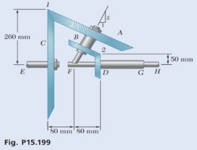
In Prob. 15.199, determine (a) the common angular acceleration of gears A and B, (b) the acceleration of the tooth of gear A that is in contact with gear C at point 1.

    Chapter 15.6, Problem 15.200P, In Prob. 15.199, determine (a) the common angular acceleration of gears A and B, (b) the

Expert Solution
Check Mark
To determine

(a)

The common angular acceleration of the gears A and B.

Answer to Problem 15.200P

The common angular acceleration of the gears A and B is (135.1rad/s2)k.

Explanation of Solution

Given Information:

The angular velocity of the gear C is 30rad/s and the angular velocity of the gear D is 20rad/s.

Draw the schematic diagram of the given system.
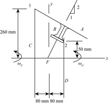
Vector Mechanics for Engineers: Dynamics, Chapter 15.6, Problem 15.200P , additional homework tip  1

Figure-(1)

Write the expression for the velocity of point 1.

v1=ωE×r1 ...... (I)

Here, the angular velocity of the gear E is ωE and the position vector at point 1 is r1.

Write the expression for the velocity of point 1 when gear C is considered to be driven by the gear unit A and B.

v1=ω×r1 ...... (II)

Here, the angular velocity of the shaft unit carries gear A and B is ω.

Write the expression for the velocity of point 2.

v2=ωG×r2 ...... (III)

Here, the angular velocity of the gear G is ωG and the position vector at point 2 is r2.

Write the expression for the velocity of point 2 when gear D is considered to be driven by the gear unit A and B.

v2=ω×r2 ...... (IV)

Write the expression for the angular velocity of the inclined shaft unit which carries gear A and B in the vector form.

ω=ωxi+ωyj+ωzk ...... (V)

Here, the angular velocity of the shaft in x- direction is ωx, the angular velocity of the shaft in y- direction is ωy and the angular velocity of the shaft in z- direction is ωz.

Draw the diagram to show the motion of the shaft is
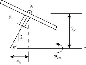
 FH.

Vector Mechanics for Engineers: Dynamics, Chapter 15.6, Problem 15.200P , additional homework tip  2

Figure-(2)

Write the expression for the velocity of point N.

vN=ω×rN ...... (VI)

Here, the position vector at point N is rN.

Write the expression for the velocity at point N when it is considered as a part of the shaft FH.

vN=ωFH×rN ...... (VII)

Here, the angular velocity of shaft FH is ωFH.

Write the expression for the common angular acceleration of the gear A and B.

α=ωFH×ω ...... (VIII)

Calculation:

Consider the unit vector along X, Y, Z axis as i, j and k.

From Figure-(1) the coordinate of the point 1 at the intersection of the gears A and C are (80mm,260mm). Therefore, the position vector at point 1 is r1=(80mm)i+(260mm)j.

From Figure-(1) the coordinate of the point 2 at the intersection of the gears B and D are (80mm,50mm). Therefore, the position vector at point 2 is r2=(80mm)i+(50mm)j.

Since, the shaft E rotate with the angular velocity of the gear C hence the velocity of the gear E in vector form is (30rad/s)i.

Substitute (30rad/s)i for ωE and (80mm)i+(260mm)j for r1 in Equation (I).

v1=(30rad/s)i[(80mm)i+(260mm)j]=|ijk30rad/s0080mm260mm0|=(00)i(00)j+(7800mm/s0)k=(7800mm/s)k

Substitute ωxi+ωyj+ωzk for ω and (80mm)i+(260mm)j for r1 in Equation (II).

v1=ωxi+ωyj+ωzk[(80mm)i+(260mm)j]=|ijkωxωyωz80mm260mm0|=(0260mmωz)i(0(80mmωz))j+(260mmωx(80mmωy))k=(260mmωz)i(80mmωz)j+(260mmωx+80mmωy)k ... (IX)

Substitute (7800mm/s)k for v1 in equation (IX).

(7800mm/s)k=[(260mmωz)i(80mmωz)j+(260mmωx+80mmωy)k] ...... (X)

Compare the terms along the x- direction in Equation (X).

(260mm)ωz=0ωz=0

Compare the terms along the z- direction in Equation (X).

(7800mm/s)=260mmωx+80mmωy ...... (XI)

Since, the shaft G rotate with the angular velocity of the gear D hence the velocity of the gear G in vector form is (20rad/s)i.

Substitute (20rad/s)i for ωG and (80mm)i+(50mm)j for r2 in Equation (III).

v2=(20rad/s)i[(80mm)i+(50mm)j]=|ijk20rad/s0080mm50mm0|=(00)i(00)j+(1000mm/s0)k=(1000mm/s)k

Substitute ωxi+ωyj+ωzk for ω and (80mm)i+(50mm)j for r2 in Equation (IV).

v2=ωxi+ωyj+ωzk[(80mm)i+(50mm)j]=|ijkωxωyωz80mm50mm0|=(050mmωz)i(0(80mmωz))j+(50mmωx(80mmωy))k=(50mmωz)i+(80mmωz)j+(50mmωx80mmωy)k ... (XII)

Substitute (1000mm/s)k for v2 in equation (XII).

(1000mm/s)k=[(50mmωz)i+(80mmωz)j+(50mmωx80mmωy)k] ...... (XIII)

Compare the terms along the z- direction in Equation (X).

(1000mm/s)=50mmωx80mmωyωx=(1000mm/s)+80mmωy(50mm) ...... (XIV)

Substitute (1000mm/s)+80mmωy(50mm) for ωx in Equation (XII).

(7800mm/s)=260mm((1000mm/s)+80mmωy(50mm))+80mmωy(7800mm/s)(5200mm/s)=496mmωyωy=(2600mm/s)496mmωy=5.24rad/s

Substitute 5.24rad/s for ωy in Equation (XI).

ωx=(1000mm/s)+80mm(5.24rad/s)(50mm)=(1000mm/s)(50mm)+80mm(5.24rad/s)(50mm)=20rad/s+8.384rad/s=28.38rad/s

Substitute 28.38rad/s for ωx, 5.24rad/s for ωy and 0 for ωz in Equation (V).

ω=(28.38rad/s)i+(5.24rad/s)j+(0)k=(28.38rad/s)i+(5.24rad/s)j

From Figure-(2) the coordinate of the point N is the half of the coordinate of y that is (12yN,yN). Therefore, the position vector at point N is rN=(1/2yN)i+(yN)j.

Substitute (28.38rad/s)i+(5.24rad/s)j for ω and (1/2yN)i+(yN)j for rN in Equation (VI).

vN=[(28.38rad/s)i+(5.24rad/s)j]((1/2yN)i+(yN)j)=|ijk28.38rad/s5.24rad/s01/2yNyN0|=(00)i(00)j+((28.387rad/s)yN(2.621rad/s)yN)k=(25.766rad/s)yNk

Substitute (ωFH)i for ωFH and (1/2yN)i+(yN)j for rN in Equation (VII).

vN=((ωFH)i)[j((1/2yN)i+(yN)j)]=|ijkωFH001/2yNyN0|=(00)i(00)j+((ωFH)yN0)k=(ωFH)yNk ...... (XV)

Substitute (25.766rad/s)yNk for vN in Equation (XV).

(25.766rad/s)yNk=(ωFH)yNkωFH=(25.766rad/s)yNkyNkωFH=(25.766rad/s)i

Substitute (25.766rad/s)i for ωFH and (28.38rad/s)i+(5.24rad/s)j for ω in equation (VIII).

α=[(25.766rad/s)i][(28.38rad/s)i+(5.24rad/s)j]=|ijk25.766rad/s0028.38rad/s5.24rad/s0|=(00)i(00)j+(135.1rad/s20)k=(135.1rad/s2)k

Conclusion:

The common angular acceleration of the gear A and B is (135.1rad/s2)k.

Expert Solution
Check Mark
To determine

(b)

The acceleration of the tooth of the gear A at point 1.

Answer to Problem 15.200P

The acceleration of the tooth of the gear A at point 1 is (5761.06mm/s2)i(232226.6mm/s2)j.

Explanation of Solution

Write the expression for the acceleration of the gear A at point 1.

a1=(α×r1)+(ω×v1) ...... (XVI)

Calculation:

Substitute (135.1rad/s2)k for α, (80mm)i+(260mm)j for r1, (7800mm/s)k for v1, (28.38rad/s)i+(5.24rad/s)j for ω in Equation (XVI).

a1=[{((135.1rad/s2)k)[(80mm)i+(260mm)j]}+{[(28.38rad/s)i+(5.24rad/s)j]((7800mm/s)k)}]=|ijk00135.1rad/s280mm260mm0|+|ijk28.38rad/s5.24rad/s0007800mm/s|={(035126mm/s2)i(0(10808mm/s2))j+(00)k+(40887.6mm/s20)i(221418.6mm/s20)j+(00)k}=(5761.06mm/s2)i(232226.6mm/s2)j

Conclusion:

The acceleration of the tooth of the gear A at point 1 is (5761.06mm/s2)i(232226.6mm/s2)j.

Want to see more full solutions like this?

Subscribe now to access step-by-step solutions to millions of textbook problems written by subject matter experts!
Students have asked these similar questions
The outer gear A rotates with an angular velocity of 6 rad/s counterclockwise. Knowing that the angular velocity of the intermediate gear B is 3 rad/s clockwise, determine: 1. The angular velocity of the arm ABC 2. The angular velocity of the outer gear C. 5 in. 10 in. C B -15 in.- -15 in.- Select one: O A. arm = 3 rad/s (CW); and @c = 1.5 rad/s (CW) O B. Warm = 5 rad/s (CW); and @c = 3 rad/s (CW) O C.o arm = 0 rad/s ; and @c = 1.5 rad/s (CCW) O D. warm = 1 rad/s (CW); and wc = 0 rad/s
1. A gear reduction system consists of three gears A, B, and C. Knowing that gear A rotates clockwise with a constant angular velocity a- 600 rpm, determine (a) the angular velocities of gears B and C, (b) the accelerations of the points on gears B and C which are in contact. 2 in. 2 in. 4 in. 6 in. 2. In the planctary gear system shown, the radius of gears A, B, C, and D is 3 in. and the radius of the outer gear E is 9 in. Knowing that gear E has an angular vekocity of 120 rpm clockwise and that the central gear has an angular velocity of 150 rpm elockwise, determine (a) the angular velocity of cach planetary gear, (b) the angular velocity of the spider connecting the planetary gears. E
3. In the planetary gear system shown the radius of gears A, B, C, and Dis 3 in. and the radius of the outer gear E is 9 in. Knowing that gear A has a constant angular velocity of 150 rpm clockwise and that the outer gear E is stationary, determine the magnitude of the acceleration of the tooth of gear D that is in contact with (a) gear A. (b) gear E. 4. Each of the gears A and B has a mass of 2.4 kg and a radius of gyration of 60 mm, while gear C has a mass of 12 kg and a radius of gyration of 150 mm. A couple Mof constant magnitude 10 Nm is applied to gear C. Determine (a) the mumber of revolutions of gear C required for its angular velocity to increase from 100 to 450 rpm, (b) the corresponding tangential force acting on gear A. S0 mm, S0 mm 200 mm

Chapter 15 Solutions

Vector Mechanics for Engineers: Dynamics

Ch. 15.1 - The angular acceleration of a shaft is defined by...Ch. 15.1 - The bent rod ABCD rotates about a line joining...Ch. 15.1 - In Prob. 15.10, determine the velocity and...Ch. 15.1 - The rectangular block shown rotates about the...Ch. 15.1 - The rectangular block shown rotates about the...Ch. 15.1 - A circular plate of 120-mm radius is supported by...Ch. 15.1 - In Prob. 15.14, determine the velocity and...Ch. 15.1 - The earth makes one complete revolution around the...Ch. 15.1 - The earth makes one complete revolution on its...Ch. 15.1 - A series of small machine components being moved...Ch. 15.1 - A series of small machine components being moved...Ch. 15.1 - The belt sander shown is initially at rest. If the...Ch. 15.1 - The rated speed of drum B of the belt sander shown...Ch. 15.1 - The two pulleys shown may be operated with the V...Ch. 15.1 - Three belts move over tow pulleys without slipping...Ch. 15.1 - gear reduction system consists of three gears A,...Ch. 15.1 - A belt is pulled to the right between cylinders A...Ch. 15.1 - Ring C has an inside radius of 55 mm and an...Ch. 15.1 - Ring B has an inside radius r2and hangs from the...Ch. 15.1 - A plastic film moves over two drums. During a 4-s...Ch. 15.1 - Cylinder A is moving downward with a velocity of 3...Ch. 15.1 - The system shown is held at rest by the...Ch. 15.1 - A load is to be raised 20 ft by the hoisting...Ch. 15.1 - A simple friction drive consists of two disks A...Ch. 15.1 - Two friction wheels A and B are both rotating...Ch. 15.1 - Two friction disks A and B are to be brought into...Ch. 15.1 - Two friction disks A and B are brought into...Ch. 15.1 - Steel tape is being wound onto a spool that...Ch. 15.1 - Prob. 15.37PCh. 15.2 - The ball rolls without slipping on the fixed...Ch. 15.2 - Three uniform rods—ABC, DCE, and FGH—are connected...Ch. 15.2 - An automobile travel, to the right at a constant...Ch. 15.2 - The motion of rod AB is guided by pins attached at...Ch. 15.2 - A painter is halfway up a 10-m ladder when the...Ch. 15.2 - Rod AB can slide freely along the floor and the...Ch. 15.2 - Rod AB can slide freely along the floor and the...Ch. 15.2 - Rod AB moves over a small wheel at C while end A...Ch. 15.2 - The disk shown moves in the xy plane. Knowing that...Ch. 15.2 - The disk shown moves in the xy p1ane. Knowing that...Ch. 15.2 - The plate shown moves in the xy plane. Knowing...Ch. 15.2 - Velocity sensors are placed on a satellite that is...Ch. 15.2 - In the planetary gear system shown, the radius of...Ch. 15.2 - In the planetary gear system shown, the radius of...Ch. 15.2 - Arm AB rotates with an angular velocity of 20...Ch. 15.2 - In the simplified sketch of a ball bearing shown,...Ch. 15.2 - A simplified gear system for a mechanical watch is...Ch. 15.2 - Arm ACB rotates about point C with an angular...Ch. 15.2 - Arm ACB rotates about point C with an angular...Ch. 15.2 - Knowing that at the instant shown the velocity of...Ch. 15.2 - Knowing that at the instant shown the angular...Ch. 15.2 - Knowing that the disk has a constant angular...Ch. 15.2 - The disk has a constant angular velocity of 20...Ch. 15.2 - The test rig is shown was developed to perform...Ch. 15.2 - In the concentric shown, a disk of 2-in. radius...Ch. 15.2 - In the engine system shown, l=160mmandb=60mm ....Ch. 15.2 - In the engine system shown, l=160 mm and b=60 mm....Ch. 15.2 - Knowing that at the instant shown the angular...Ch. 15.2 - In the position shown, bar AB has angular velocity...Ch. 15.2 - Linkage DBEF is part of a windshield wiper...Ch. 15.2 - Roberts linkage is named after Richard Roberts...Ch. 15.2 - Roberts linkage is named after Richard Roberts...Ch. 15.2 - In the position shown, bar DE has a constant...Ch. 15.2 - In the position shown, bar DE has a constant...Ch. 15.2 - Both 6-in.-radius wheels roll without slipping on...Ch. 15.2 - The 80-mm-radius wheel shown rolls to the left...Ch. 15.2 - For the gearing shown, derive an expression for...Ch. 15.3 - The disk rolls without sliding on the fixed...Ch. 15.3 - Bar BDE is pinned to two links, AB and CD. At the...Ch. 15.3 - A juggling club is thrown vertically into the air....Ch. 15.3 - At the instant shown during deceleration, the...Ch. 15.3 - A helicopter moves horizontally in the x direction...Ch. 15.3 - A 60-mm-radius drum is rigidly attached to a...Ch. 15.3 - Prob. 15.77PCh. 15.3 - The spool of tape shown and its frame assembly are...Ch. 15.3 - The spool of tape shown and its frame are pulled...Ch. 15.3 - The arm ABC rotates with an angular velocity of 4...Ch. 15.3 - The double gear rolls on the stationary left rack...Ch. 15.3 - An overhead door is guided by wheels at A and B...Ch. 15.3 - Rod ABD is guided by wheels at A and B that roll...Ch. 15.3 - Rod BDE is partially guided by a roller at D that...Ch. 15.3 - Rod BDE is partially guided by a roller at D that...Ch. 15.3 - A motor at O drives the windshield wiper mechanism...Ch. 15.3 - A motor at O drives the windshield wiper mechanism...Ch. 15.3 - Rod AB can slide freely along the floor and the...Ch. 15.3 - Small wheels have been attached to the ends of bar...Ch. 15.3 - Two slots have been cut in plate FG and the plate...Ch. 15.3 - The disk is released from rest and rolls down the...Ch. 15.3 - The pin at B is attached to member ABD and can...Ch. 15.3 - Two identical rods ABF and DBE are Connected by a...Ch. 15.3 - Ann ABD is connected by pins to a collar at B and...Ch. 15.3 - Two 25-in. rods are pin-connected at D as shown....Ch. 15.3 - Two rods ABD and DE are connected to three collars...Ch. 15.3 - At the instant shown, the velocity of collar A is...Ch. 15.3 - Two rods AB and DE are connected as shown. Knowing...Ch. 15.3 - Describe the space centrode and the body centrode...Ch. 15.3 - Describe the space centrode and the body centrode...Ch. 15.3 - Using the method of Sec. 15.3, solve Prob. 15.60.Ch. 15.3 - Using the method of Sec. 15.3, solve Prob. 15.64.Ch. 15.3 - Using the method of Sec. 15.3, solve Prob. 15.65.Ch. 15.3 - Using the method of Sec. 15.3, solve Prob. 15.38.Ch. 15.4 - A rear-wheel-drive car starts from rest and...Ch. 15.4 - A 5-m steel beam is lowered by means of two cables...Ch. 15.4 - For a 5-m steel beam AE, the acceleration of point...Ch. 15.4 - A 900-mm rod rests on a horizontal table A force P...Ch. 15.4 - In Prob. 15.107, determine the point of the rod...Ch. 15.4 - Knowing that at the instant shown crank BC has a...Ch. 15.4 - End A of rod AB moves to the right with a constant...Ch. 15.4 - An automobile travels to the left at a constant...Ch. 15.4 - The 18-in.-radius flywheel is rigidly attached to...Ch. 15.4 - A 3-in.-radius drum is rigidly attached to a...Ch. 15.4 - A 3-in.-radius drum is rigidly attached to a...Ch. 15.4 - A heavy crate is being moved a sbo1 distance using...Ch. 15.4 - A wheel rolls without slipping on a fixed...Ch. 15.4 - The 100-nun-radius drum rolls without slipping on...Ch. 15.4 - In the planetary gear system shown, the radius of...Ch. 15.4 - The 200-mm-radius disk rolls without sliding on...Ch. 15.4 - Knowing that crank AB rotates about point A with a...Ch. 15.4 - Knowing that crank AB rotates about point A with a...Ch. 15.4 - In the two-cylinder air compressor shown, the...Ch. 15.4 - The disk shown has a constant angular velocity of...Ch. 15.4 - Arm AB has a constant angular velocity of 16 rad/s...Ch. 15.4 - Arm AB has a constant angular velocity of 16 rad/s...Ch. 15.4 - A straight rack rests on a gear of radius r=3 in....Ch. 15.4 - The elliptical exercise machine has fixed axes of...Ch. 15.4 - The elliptical exercise machine has fixed axes of...Ch. 15.4 - Knowing that at the instant shown bar AB has a...Ch. 15.4 - Knowing that at the instant shown bar DE has a...Ch. 15.4 - Knowing that at the instant shown bar AB has a...Ch. 15.4 - Knowing that at the instant shown bar AB has a...Ch. 15.4 - Knowing that at the instant shown bar AB has...Ch. 15.4 - Knowing that at the instant shown bar AB has...Ch. 15.4 - Roberts linkage is named after Richard Roberts...Ch. 15.4 - For the oil pump rig shown, link AB causes the...Ch. 15.4 - Denoting by rA the position vector of a point A of...Ch. 15.4 - The drive disk of the Scotch crosshead mechanism...Ch. 15.4 - The wheels attached to the ends of rod AB roll...Ch. 15.4 - The wheels attached to the ends of rod AB roll...Ch. 15.4 - A disk of radius r rolls to the right with a...Ch. 15.4 - Rod AB moves over a small wheel at C while end A...Ch. 15.4 - Rod AB moves over a small wheel at C while end A...Ch. 15.4 - Crank4B rotates with a constant c1ockise angular...Ch. 15.4 - Crank 4B rotates with a constant clockwise angular...Ch. 15.4 - Solve the engine system from Sample Prob. 15.15...Ch. 15.4 - The position of rod AB is controlled by a disk of...Ch. 15.4 - A wheel of radius r rolls without slipping along...Ch. 15.4 - In Prob. 15. 148, show that the path of P is a...Ch. 15.5 - A person walks radially inward on a platform that...Ch. 15.5 - Pin P is attached to the collar shown; the motion...Ch. 15.5 - Pin P is attached to the collar shown; the motion...Ch. 15.5 - Two rotating rods are connected by slider block P....Ch. 15.5 - Two rotating rods are connected by slider block P....Ch. 15.5 - Pin P is attached to the wheel shown and slides in...Ch. 15.5 - Knowing that at the instant shown the angular...Ch. 15.5 - Knowing that at the instant shown the anu1ar...Ch. 15.5 - The motion of pin P is guided by slots cut in...Ch. 15.5 - Four pins slide in four separate slots cut in a...Ch. 15.5 - Solve Prob. 15.158, assuming that the plate...Ch. 15.5 - The cage of a mine elevator moves downward at a...Ch. 15.5 - Prob. 15.161PCh. 15.5 - A rocket sled is tested o a straight track that is...Ch. 15.5 - Prob. 15.163PCh. 15.5 - Prob. 15.164PCh. 15.5 - At the instant shown the length of the boom AB is...Ch. 15.5 - In the automated welding setup shown, the position...Ch. 15.5 - In the automated welding setup shown, the position...Ch. 15.5 - A chain is looped around two gears of radius 40 mm...Ch. 15.5 - A chain is looped around two gears of radius 40 mm...Ch. 15.5 - Prob. 15.170PCh. 15.5 - The human leg can be crudely approximated as two...Ch. 15.5 - The collar P slides outward at a constant relative...Ch. 15.5 - Pin P slides in a circular slot cut in the plate...Ch. 15.5 - Rod AD is bent in the shape of an are of a circle...Ch. 15.5 - Solve Prob. 15.l74 when =90 .Ch. 15.5 - Prob. 15.176PCh. 15.5 - Prob. 15.177PCh. 15.5 - In Prob. 15.177, determine the angular velocity...Ch. 15.5 - Prob. 15.179PCh. 15.5 - Prob. 15.180PCh. 15.5 - Rod AB passes through a collar that is welded to...Ch. 15.5 - Solve Prob. 15.181 assuming block A moves to the...Ch. 15.5 - In Prob. 15.157, determine the acceleration of pin...Ch. 15.6 - The bowling ball shown rolls without slipping on...Ch. 15.6 - The bowling ball shown rolls without slipping on...Ch. 15.6 - Plate ABD and rod OB are rigidly connected and...Ch. 15.6 - At the instant considered, the radar antenna shown...Ch. 15.6 - Prob. 15.188PCh. 15.6 - The disk of a portable sander rotates at the...Ch. 15.6 - Prob. 15.190PCh. 15.6 - Prob. 15.191PCh. 15.6 - In the system shown, disk A is free to rotate...Ch. 15.6 - Prob. 15.193PCh. 15.6 - A gun barrel of length OP=4m is mounted on a...Ch. 15.6 - Prob. 15.195PCh. 15.6 - A 3-in-radius disk spins at the constant rate 2=4...Ch. 15.6 - The cone shown rolls on the zx plane with its apex...Ch. 15.6 - At the instant shown, the robotic arm ABC is being...Ch. 15.6 - In the planetary gear system shown, gears A and B...Ch. 15.6 - In Prob. 15.199, determine (a) the common angular...Ch. 15.6 - Several rods are brazed together to form the...Ch. 15.6 - In Prob. 15.201, the speed of point B is known to...Ch. 15.6 - Rod AB of length 25 in. is connected by ball...Ch. 15.6 - Rod AB has a length of 13 in. and is connected by...Ch. 15.6 - Rod BC and BD are each 840 mm long and are...Ch. 15.6 - Rod AB is connected by ball-and-socket joints to...Ch. 15.6 - Rod AB of length 29 in. is connected by...Ch. 15.6 - Rod AB of length 300 mm is connected by ball...Ch. 15.6 - Rod AB of length 300 mm is connected by...Ch. 15.6 - Two shafts AC and EG, which lie in the vertical yz...Ch. 15.6 - Solve Prob. 15.210, assuming that the arm of the...Ch. 15.6 - Rod BC has a length of 42 in. and is connected by...Ch. 15.6 - Rod AB has a length of 275 mm and is connected by...Ch. 15.6 - For the mechanism of Prob.15.204, determine the...Ch. 15.6 - In Prob. 15.205, determine the acceleration of...Ch. 15.6 - In Prob. 15.206, determine the acceleration of...Ch. 15.6 - In Prob. 15.207, determine the acceleration of...Ch. 15.6 - In Prob. 15.208, determine the acceleration of...Ch. 15.6 - In Prob. 15.209, determine the acceleration of...Ch. 15.7 - A flight simulator is used to train pilots on how...Ch. 15.7 - A flight simulator is used to train pilots on how...Ch. 15.7 - The rectangular plate shown rotates at the...Ch. 15.7 - The rectangular plate shown rotates at the...Ch. 15.7 - Rod AB is welded to the 0.3-m-radius plate that...Ch. 15.7 - The bent rod shown rotates at the constant rate of...Ch. 15.7 - The bent pipe shown rotates at the constant rate...Ch. 15.7 - The circular plate shown rotates about its...Ch. 15.7 - Manufactured items are spray-painted as they pass...Ch. 15.7 - Solve Prob. 15.227, assuming that at the instant...Ch. 15.7 - Solve Prob. 15.225, assuming that at the instant...Ch. 15.7 - Using the method of Sec. 15.7A, solve Prob....Ch. 15.7 - Using the method of Sec. 15.7A, solve Prob....Ch. 15.7 - Using the method of Sec. 15.7A, solve Prob....Ch. 15.7 - The 400-mm bar AB is made to rotate at the...Ch. 15.7 - The 400-mm bar AB is made to rotate at the rate...Ch. 15.7 - The arm AB of length 16 ft is used to provide an...Ch. 15.7 - The remote manipulator system (RMS) shown is used...Ch. 15.7 - A disk with a radius of 120 mm rotates at the...Ch. 15.7 - The crane shown rotates at the constant rate...Ch. 15.7 - The vertical plate shown is welded to arm EFG, and...Ch. 15.7 - The vertical plate shown is welded to arm EFG, and...Ch. 15.7 - A disk of 180-mm radius rotates at the constant...Ch. 15.7 - A disk of 180-mm radius rotates at the constant...Ch. 15.7 - A square plate of side 2r is welded to a vertical...Ch. 15.7 - Two disks, each of 130-mm radius, are welded to...Ch. 15.7 - In Prob. 15.245, determine the velocity and...Ch. 15.7 - The position of the stylus tip A is controlled by...Ch. 15 - A wheel moves in the xy plane in such a way that...Ch. 15 - Two blocks and a pulley e connected by...Ch. 15 - A baseball pitching machine is designed to deliver...Ch. 15 - Knowing that inner gear A is stationary and outer...Ch. 15 - Knowing that at the instant shown bar AB has an...Ch. 15 - Knowing that at the instant shown rod AB has zero...Ch. 15 - Rod AB is attached to a collar at A and is fitted...Ch. 15 - flows through a curved pipe .AB that rotates with...Ch. 15 - A disk of 0.15-m radius rotates at the constant...Ch. 15 - Two rods AE and BD pass through holes drilled into...Ch. 15 - Rod BC of length 24 in. is connected by ball...Ch. 15 - In the positions shown, the thin rod moves at a...
Knowledge Booster
Background pattern image
Mechanical Engineering
Learn more about
Need a deep-dive on the concept behind this application? Look no further. Learn more about this topic, mechanical-engineering and related others by exploring similar questions and additional content below.
Similar questions
SEE MORE QUESTIONS
Recommended textbooks for you
Text book image
Elements Of Electromagnetics
Mechanical Engineering
ISBN:9780190698614
Author:Sadiku, Matthew N. O.
Publisher:Oxford University Press
Text book image
Mechanics of Materials (10th Edition)
Mechanical Engineering
ISBN:9780134319650
Author:Russell C. Hibbeler
Publisher:PEARSON
Text book image
Thermodynamics: An Engineering Approach
Mechanical Engineering
ISBN:9781259822674
Author:Yunus A. Cengel Dr., Michael A. Boles
Publisher:McGraw-Hill Education
Text book image
Control Systems Engineering
Mechanical Engineering
ISBN:9781118170519
Author:Norman S. Nise
Publisher:WILEY
Text book image
Mechanics of Materials (MindTap Course List)
Mechanical Engineering
ISBN:9781337093347
Author:Barry J. Goodno, James M. Gere
Publisher:Cengage Learning
Text book image
Engineering Mechanics: Statics
Mechanical Engineering
ISBN:9781118807330
Author:James L. Meriam, L. G. Kraige, J. N. Bolton
Publisher:WILEY
Power Transmission; Author: Terry Brown Mechanical Engineering;https://www.youtube.com/watch?v=YVm4LNVp1vA;License: Standard Youtube License