Concept explainers
Videos
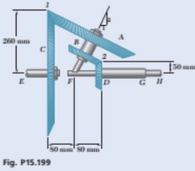
In the planetary gear system shown, gears A and B are rigidly connected to each other and rotate as a unit about the inclined shaft. Gears C and D rotate with constant angular velocities of 30 rad/s and 20 rad/s, respectively (both counterclockwise when viewed from the right). Choosing the x axis to the right, the y axis upward, and the z axis pointing out of the plane of the figure, determine (a) the common angular velocity of gears A and B, (b) the angular velocity of shaft FH, which is rigidly attached to the inclined shaft.
(a)
The common angular velocity of the gears
Answer to Problem 15.199P
The common angular velocity of the gears
Explanation of Solution
Given Information:
The angular velocity of the gear
Draw the schematic diagram of the given system.
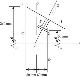
Figure-(1)
Write the expression for the velocity of point 1.
Here, the angular velocity of the gear
Write the expression for the velocity of point 1 when gear
Here, the angular velocity of the shaft unit carries gear
Write the expression for the velocity of point 2.
Here, the angular velocity of the gear
Write the expression for the velocity of point 2 when gear
Write the expression for the angular velocity of the inclined shaft unit which carries gear
Here, the angular velocity of the shaft in x- direction is
Calculation:
Consider the unit vector along
From Figure-(1) the coordinate of the point 1 at the intersection of the gears
From Figure-(1) the coordinate of the point 2 at the intersection of the gears
Since, the shaft
Substitute
Substitute
Substitute
Compare the terms along the x- direction in Equation (VII).
Compare the terms along the z- direction in Equation (VII).
Since, the shaft
Substitute
Substitute
Substitute
Compare the terms along the z- direction in Equation (X).
Substitute
Substitute
Substitute
Conclusion:
The common angular velocity of the gear
(b)
The angular velocity of the shaft
Answer to Problem 15.199P
The angular velocity of the shaft
Explanation of Solution
Draw the diagram to show the motion of the shaft is
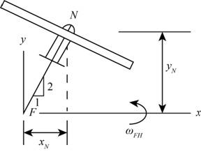
Figure-(2)
Write the expression for the velocity of point
Here, the position vector at point
Write the expression for the velocity at point
Here, the angular velocity of shaft
Calculation:
From Figure-(2) the coordinate of the point
Substitute
Substitute
Substitute
Conclusion:
The angular velocity of the shaft
Want to see more full solutions like this?
Chapter 15 Solutions
Vector Mechanics for Engineers: Dynamics


- In the image on the right, there is a red gear G1 on the left with a radius of r1 = 2.81cm. Gear G1 is locked to the green gear G2 with a radius of r2 = 0.734cm. Gear G2 then shares the same axle as the blue circular saw G3, which has a radius of r3 known to make a full rotation every T = 0.836s. Using at least 6 significant digits in your calculations, compute the following: V3! 12.8cm. Gear G1 is W1 a) The angular speed wi of gear G1. Remember that angular speed is measured in radians per T3 r2 unit time. G2 b) The rim speed vi of gear G1. Since gears G1 and G2 are locked together, the rim speed of G2 is also v1. G1 G3 c) The angular speed w2 of gear G2. Since gear G2 and saw G3 share the same axle, the angular speed of G3 is also w2. d) The rim speed v3 of saw G3.arrow_forward(Three-Dimensional Motion) The figure below represents a pair of bevel gears A and B. Gear A rotates in ahorizontal plane about a vertical axis at O. Gear B rotates around the shaft OC,which in turn rotates about the terminal axis at O. At the instant shown, theangular velocity of the shaft OC is 10j rad/sec, and gear A is stationary. Deter-mine the angular velocity of gear B, and the velocity of a point D at the top ofgear B.arrow_forwardThere are two adjacent gears A and B, with 23 and 42 teeth respectively. Initially, both gears are only rotating, with A rotating clockwise with angular velocity 1 rad/s, and B rotating counterclockwise. When making complex decisions, gear A's angular speed increases while gear B maintains its angular speed. As a result, gear A rolls without slipping around the circumference of gear B. If it takes 1 second for gear A to complete 1 revolution around gear B, then what's the new angular velocity of gear A? Answer in rad/s and 3 Significant Figures. Make sure to use the proper sign convention (CW : - :: CCW : +).arrow_forward
- Gear A on the drive shaft of the outboard motor has a radius ra=9 in. and the meshed pinion gear B on the propeller shaft has a radius rg-53 in. The point P is located on the propeller's tip at a distance 4 in. from the neutral axis of the propeller's shaft. نند P B At the beginning of the propulsion, the drive shaft rotates with an angular acceleration a = A. t 2.0 rad.s2 where t is in seconds. what must be the value of A to have, while starting from rest, vp=24 in.s¹¹ in 6 seconds ?arrow_forwardThe figure below represents a pair of bevel gears A and B. Gear A rotates in ahorizontal plane about a vertical axis at O. Gear B rotates around the shaft OC,which in turn rotates about the terminal axis at O. At the instant shown, theangular velocity of the shaft OC is 10j rad/sec. If gear A has an angular velocityof 4j rad/sec, determine the angular velocity of gear B.arrow_forwardProblem (3) radius r = 70 mm and is attached to block B as shown. If the angular velocity of gear D is 20 rpm A straight rack rests on a gear of A counterclockwise when 0 = 20°, determine: (a) The velocity of block B (b) The angular velocity of rack AB Solve the problem one time using the relative velocity equation and another time using the Instantaneous Center (IC) method. You should get the same answers.arrow_forward
- Q2) For the system shown in the figure, o, - 15 rad/s. Determine the angular velocities of the links C and AB. mm O O 20° 240 mm (o A 80 mm 60° wwww. lowing down at a rate of 3 marrow_forwardIn the given planetary gear system, the free end of Driving Shaft E has an angular velocity of we = 11.2345 rpm, CCW with respect to the point of view from Point A. The radius of the tree Planet gears is B = 40 mm, sun gear D = 60 mm, and ring gear C = 140 mm. The centers of the three planet gears B are pin connected to carrier A, which is one whole rigid body. The three planet gears B are allowed only to spin and not to turn. Determine the: angular velocity (in rpm) of the carrier A angular velocity (in rpm) of ring gear C and the angular velocity (in rpm) of each planet gear B Driving Shaft E Sun Gear D 3 Planetary Gears B Carrier A Ring Gear Carrow_forwardGear 2: N2 = 25 teeth and Pd = 20 per in Gear 3: d3 = 3.5 in Gear 4: N4 = 28 teeth Gear 5: d5 = 4 in and Pd = 16 per in Gear 6: d6 = 3 in and Pd = 10 per in Gear 7: N7 = 48 teeth Determine the rotational velocity of gear 2 as gear 7 drives at 200 rev/min counterclockwise (CCW). Determine the center distance between the shafts that carry gears 2 and 7.arrow_forward
- Find: angular velocity of gear B (omega B) when t = 2 seconds. and Displacement of gear B (teta B) when t = 2 seconds.arrow_forwardA simplified gear system for a mechanical watch is shown. Know that gear A has a constant angular velocity of 1 rev/h and gear Chas a constant angular velocity of 1 rpm. Given: dh=0.5 in. and ch=0.37 in. d2 A. d1 Determine the radius r. (You must provide an answer before moving on to the next part.) The radius ris in.arrow_forwardIn the mechanism shown below, the wheel is pinned at the center. The radius from O to C is 0.2 m and link CB is 0.55 m long. CB makes an initial angle of 25° with the horizontal as shown. The hydraulic ram at B is moving left at 7 m/s. At the moment shown, what is the angular velocity of link BC and the wheel pivoted at 0? 0000 Ninbet tatis rad/sarrow_forward
 Elements Of ElectromagneticsMechanical EngineeringISBN:9780190698614Author:Sadiku, Matthew N. O.Publisher:Oxford University Press
 Mechanics of Materials (10th Edition)Mechanical EngineeringISBN:9780134319650Author:Russell C. HibbelerPublisher:PEARSON
 Thermodynamics: An Engineering ApproachMechanical EngineeringISBN:9781259822674Author:Yunus A. Cengel Dr., Michael A. BolesPublisher:McGraw-Hill Education
 Control Systems EngineeringMechanical EngineeringISBN:9781118170519Author:Norman S. NisePublisher:WILEY
 Mechanics of Materials (MindTap Course List)Mechanical EngineeringISBN:9781337093347Author:Barry J. Goodno, James M. GerePublisher:Cengage Learning
 Engineering Mechanics: StaticsMechanical EngineeringISBN:9781118807330Author:James L. Meriam, L. G. Kraige, J. N. BoltonPublisher:WILEY