
Mechanics of Materials
11th Edition
ISBN: 9780137605460
Author: Russell C. Hibbeler
Publisher: Pearson Education (US)
expand_more
expand_more
format_list_bulleted
Concept explainers
Videos
Textbook Question
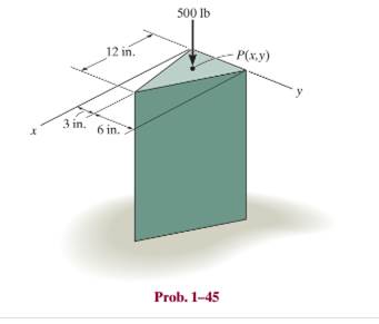
Chapter 1.5, Problem 45P
If the pedestal is subjected to a compressive force of 500 lb. specify the x and y coordinates for the location of point
Expert Solution & Answer
Want to see the full answer?
Check out a sample textbook solution
Students have asked these similar questions
The horizontal force of P = 80 KN acts at the end of the plate. The plate has a thickness of 10 mm and P acts along the centerline of this thickness such that d = 50 mm. Plot the distribution of normal stress acting along section a-a.
The screw of the clamp exerts a compressive force of 500 lb on the woodblocks. Sketch the stress distribution along section a–a of the clamp. The cross section is rectangular, 0.75 in. by 0.50 in.
In each case, the state of stress sx, sy, txy produces normal and shear stress components along section AB of the element that have values of sx = -5 kPa and tx y = 8 kPa when calculated using the stress transformation equations.Establish the x and y axes for each segment and specify the angle u, then show these results acting on each segment.
Chapter 1 Solutions
Mechanics of Materials
Ch. 1.2 - Determine the resultant internal normal force,...Ch. 1.2 - Determine the resultant internal normal force,...Ch. 1.2 - Determine the resultant internal normal force,...Ch. 1.2 - Determine the resultant internal normal force,...Ch. 1.2 - Determine the resultant internal normal force,...Ch. 1.2 - Determine the resultant internal normal force,...Ch. 1.2 - The shaft is supported by a smooth thrust bearing...Ch. 1.2 - Determine the resultant internal normal and shear...Ch. 1.2 - Determine the resultant internal torque acting on...Ch. 1.2 - Determine the resultant internal loadings in the...
Ch. 1.2 - The shaft is supported by a smooth thrust bearing...Ch. 1.2 - Determine the resultant internal loading on the...Ch. 1.2 - Determine the resultant internal loading on the...Ch. 1.2 - The 800-lb load is being hoisted at a constant...Ch. 1.2 - Determine resultant internal loadings acting on...Ch. 1.2 - Determine the resultant internal normal force...Ch. 1.2 - Determine the resultant internal loadings on the...Ch. 1.2 - Determine the resultant internal loadings on the...Ch. 1.2 - The blade of the hacksaw is subjected to a...Ch. 1.2 - The blade of the hacksaw is subjected to a...Ch. 1.2 - Determine the resultant internal loadings on the...Ch. 1.2 - Determine the resultant internal loadings on the...Ch. 1.2 - The sky hook is used to support the cable of a...Ch. 1.2 - Determine the resultant internal torque acting on...Ch. 1.2 - Determine the resultant internal loadings acting...Ch. 1.2 - Determine the resultant internal loadings on the...Ch. 1.2 - Determine the resultant internal loadings on the...Ch. 1.2 - The metal stud punch is subjected to a force of...Ch. 1.2 - The metal stud punch is subjected to a force of...Ch. 1.2 - Determine the resultant internal loadings acting...Ch. 1.2 - A force of 80 N is supported by the bracket....Ch. 1.2 - The curved rod has a radius r and is fixed to the...Ch. 1.2 - The pipe assembly is subjected to a force of 600 N...Ch. 1.2 - If the drill bit jams when the handle of the hand...Ch. 1.2 - The curved rod AD of radius r has a weight per...Ch. 1.2 - A differential element taken from a curved bar is...Ch. 1.5 - The uniform beam is supported by two rods AB and...Ch. 1.5 - Determine the average normal stress on the cross...Ch. 1.5 - Determine the average normal stress on the cross...Ch. 1.5 - If the 600-kN force acts through the centroid of...Ch. 1.5 - Determine the average normal stress at points A,...Ch. 1.5 - Determine the average normal stress in rod AB if...Ch. 1.5 - A 175-lb woman stands on a vinyl floor wearing...Ch. 1.5 - Determine the largest intensity w of the uniform...Ch. 1.5 - The specimen failed in a tension test at an angle...Ch. 1.5 - The built-up shaft consists of a pipe AB and solid...Ch. 1.5 - If the material fails when the average normal...Ch. 1.5 - If the block is subjected to a centrally applied...Ch. 1.5 - The plate has a width of 0.5 m. If the stress...Ch. 1.5 - The member is subjected to a tensile force of 200...Ch. 1.5 - The boom has a uniform weight of 600 lb and is...Ch. 1.5 - Determine the average normal stress in each of the...Ch. 1.5 - If the average normal stress in each of the...Ch. 1.5 - Determine the maximum average shear stress in pin...Ch. 1.5 - The 150-kg bucket is suspended from end E of the...Ch. 1.5 - The 150-kg bucket is suspended from end E of the...Ch. 1.5 - If the pedestal is subjected to a compressive...Ch. 1.5 - The beam is supported by two rods AB and CD that...Ch. 1.5 - The beam is supported by two rods AB and CD that...Ch. 1.5 - The beam is supported by a pin at B and a short...Ch. 1.5 - The railcar docklight is supported by the...Ch. 1.5 - The plastic block is subjected to an axial...Ch. 1.5 - During a tension test, the wooden specimen is...Ch. 1.5 - The bar has a cross-sectional area of 400(106) m2....Ch. 1.5 - The bar has a cross-sectional area of 400(106) m2....Ch. 1.5 - Prob. 54PCh. 1.5 - The 2-Mg concrete pipe has a center of mass at...Ch. 1.5 - The 2-Mg concrete pipe has a center of mass at...Ch. 1.5 - The pier is made of material having a specific...Ch. 1.5 - Prob. 58PCh. 1.5 - The uniform bar, having a cross-sectional area of...Ch. 1.5 - Prob. 60PCh. 1.5 - Prob. 61PCh. 1.5 - The triangular blocks are glued along each side of...Ch. 1.5 - The triangular blocks are glued along each side of...Ch. 1.5 - Prob. 64PCh. 1.5 - Determine the maximum magnitude P of the load the...Ch. 1.5 - Prob. 66PCh. 1.5 - Prob. 67PCh. 1.7 - Rods AC and BC are used to suspend the 200-kg...Ch. 1.7 - If it is subjected to double shear, determine the...Ch. 1.7 - Determine the maximum average shear stress...Ch. 1.7 - If each of the three nails has a diameter of 4 mm...Ch. 1.7 - The strut is glued to the horizontal member at...Ch. 1.7 - Determine the maximum average shear stress...Ch. 1.7 - If the eyebolt is made of a material having a...Ch. 1.7 - If the bar assembly is made of a material having a...Ch. 1.7 - Determine the maximum force P that can be applied...Ch. 1.7 - The pin is made of a material having a failure...Ch. 1.7 - If the bolt head and the supporting bracket are...Ch. 1.7 - Six nails are used to hold the hanger at A against...Ch. 1.7 - If A and B are both made of wood and are 38 in....Ch. 1.7 - Prob. 70PCh. 1.7 - The connection is made using a bolt and nut and...Ch. 1.7 - Determine the required cross-sectional area of...Ch. 1.7 - Prob. 73PCh. 1.7 - The spring mechanism is used as a shock absorber...Ch. 1.7 - Prob. 75PCh. 1.7 - The hangers support the joist in such a way that...Ch. 1.7 - Prob. 77PCh. 1.7 - Prob. 78PCh. 1.7 - The two aluminum rods AB and BC have diameters of...Ch. 1.7 - The cotter is used to hold the two rods together....Ch. 1.7 - Prob. 81PCh. 1.7 - The 60mm60mm oak post is supported on the pine...Ch. 1.7 - Prob. 83PCh. 1.7 - Prob. 84PCh. 1.7 - The assembly consists of three disks A, B, and C...Ch. 1.7 - Prob. 86PCh. 1.7 - Prob. 87PCh. 1.7 - Prob. 88PCh. 1.7 - Prob. 89PCh. 1.7 - Prob. 90PCh. 1.7 - Prob. 91PCh. 1.7 - Prob. 92PCh. 1.7 - Prob. 93PCh. 1.7 - The aluminum bracket A is used to support the...Ch. 1.7 - If the allowable tensile stress for the bar is...Ch. 1.7 - The bar is connected to the support using a pin...Ch. 1 - The beam AB is pin supported at A and supported by...Ch. 1 - The long bolt passes through the 30-mm-thick...Ch. 1 - Determine the required thickness of member BC to...Ch. 1 - The circular punch B exerts a force of 2 kN on the...Ch. 1 - Determine the average punching shear stress the...Ch. 1 - The 150 mm by 150 mm block of aluminum supports a...Ch. 1 - The yoke-and-rod connection is subjected to a...Ch. 1 - The cable has a specific weight (weight/volume)...
Knowledge Booster


Learn more about
Need a deep-dive on the concept behind this application? Look no further. Learn more about this topic, mechanical-engineering and related others by exploring similar questions and additional content below.Similar questions
- X A purse hook is used to hang a handbag from the edge of a table with L = 50 mm. If the cross section at a-a has a diameter of d = 3 mm and the hook is supporting a purse with a mass of 3 kg, determine the normal stress profile. For what value of y (using the coordinates pictured for section a-a) with the normal stress be zero. If it is never zero enter "nde" for "not defined". N -L→ a. a AB C Follow sign convention that tension is positive and compression is negative. Normal stress at point A, σA= MPa Normal stress at point B, σB = MPa Normal stress at point C, σc = MPa y position where normal stress equals zero = mm Section a-a darrow_forwardThe box beam is subjected to the 26-kN force that is applied at the center of its width, 75 mm from each side. Determine the principal stresses at point A and show the results in an element located at this point. Use the shear formula to calculate the shear stress.arrow_forwardThe book is subjected to the force of 60 lb Determine the state of stress at point A at section a-a. The cross section is circular and has a diameter of 0.5 in. Use the curved-beam formula to compute the bending stress (Figure 1) Figure 1.5 in. 13 45° B 1 of 1 > ▾ Part A Determine the normal stress. Express your answer using three significant figures and include the appropriate units. Enter negative value in the case of compression and positive value in the case of tension. g= Value Submit Part B ← A psi Previous Answers Request Answer X Incorrect; Try Again; 4 attempts remaining ✓ Correct < Return to Assignment Ċ 129 ? Determine the shear stress Express your answer using three significant figures and include the appropriate units. T= 0 psi Previous Answers Provide Feedbackarrow_forward
- The bent pipe has a 1.5-in. outer diameter and a 0.2-in. wall thickness. Calculate the largest shear stress that occurs in (a) segment BC; and (b) segment AB. Neglect the stress due to the transverse shear force.arrow_forwardThe solid bar has a diameter of 50 mm. The two forces and the torque Tx are acting at the origin of the x-y-z coordinate system which is coincident with the centroid of the cross-section of the bar; the 1800 N force is acting in the y-z plane and torque Tx is acting about the x-axis. Determine the state of stress at points A and B, and show the respective stress components acting on differential elements located at these two points. 200 mm/ y 200 mm 1200 N Tx = 40 N.m %3D 1800 Narrow_forwardThe solid bar has a diameter of 50 mm. The two forces and the torque Tx are acting at the origin of the x-y-z coordinate system which is coincident with the centroid of the cross-section of the bar; the 1800 N force is acting in the y-z plane and torque T is acting about the x-axis. Determine the state of stress at points A and B, and show the respective stress components acting on differential elements located at these two points. {30 marks} 200 mm y 200 mm B. 1200 N T= 40 N.m 1800 Narrow_forward
- The bent shaft is fixed in the wall at A. If a force F is applied at B (the force is acting on the plane parallel to the x-o-y plane). Take F = 54 N and 0 = 45°. 1. Determine the internal forces acting on the section containing points D and E 2. Determine the normal stress component acting at point E 3. Determine the shear stress component developed at point E 4. Draw the state of stress on a volume element (stress element) located at point E 5. Determine the principal stresses acting at point E by constructing Mohr's circle A 150 mm E 200 mm 30 mm 75 mm B Farrow_forwardIf the allowable normal stress is 120MPa and the allowable shear stress is 60MPa, what is the resultant force at the support A?arrow_forward1. The pictured link acts as a part of the elevator control for a small airplane. If the attached aluminum tube has an inner diameter of 25 mm and a wall thickness of 5 mm, determine the shear stress in the outer and inner surfaces of the tube when a cable force of 600 N is applied to the cables. Also, sketch the shear-stress distribution over the cross-section.arrow_forward
- The forces applied to pulleys are given as shown below. Accordingly, show the stress state at point A on a 2-dimensional stress element and find the Von-Misses equivalent stress.arrow_forwardUse Mohr’s circle to determine the principal stresses at the point. Also, find the corresponding orientation of the element with respect to the element shown.arrow_forwardDetermine the absolute shear stress for point K.arrow_forward
arrow_back_ios
SEE MORE QUESTIONS
arrow_forward_ios
Recommended textbooks for you
 Elements Of ElectromagneticsMechanical EngineeringISBN:9780190698614Author:Sadiku, Matthew N. O.Publisher:Oxford University Press
 Mechanics of Materials (10th Edition)Mechanical EngineeringISBN:9780134319650Author:Russell C. HibbelerPublisher:PEARSON
 Thermodynamics: An Engineering ApproachMechanical EngineeringISBN:9781259822674Author:Yunus A. Cengel Dr., Michael A. BolesPublisher:McGraw-Hill Education
 Control Systems EngineeringMechanical EngineeringISBN:9781118170519Author:Norman S. NisePublisher:WILEY
 Mechanics of Materials (MindTap Course List)Mechanical EngineeringISBN:9781337093347Author:Barry J. Goodno, James M. GerePublisher:Cengage Learning
 Engineering Mechanics: StaticsMechanical EngineeringISBN:9781118807330Author:James L. Meriam, L. G. Kraige, J. N. BoltonPublisher:WILEY
Elements Of Electromagnetics
Mechanical Engineering
ISBN:9780190698614
Author:Sadiku, Matthew N. O.
Publisher:Oxford University Press
Mechanics of Materials (10th Edition)
Mechanical Engineering
ISBN:9780134319650
Author:Russell C. Hibbeler
Publisher:PEARSON
Thermodynamics: An Engineering Approach
Mechanical Engineering
ISBN:9781259822674
Author:Yunus A. Cengel Dr., Michael A. Boles
Publisher:McGraw-Hill Education
Control Systems Engineering
Mechanical Engineering
ISBN:9781118170519
Author:Norman S. Nise
Publisher:WILEY
Mechanics of Materials (MindTap Course List)
Mechanical Engineering
ISBN:9781337093347
Author:Barry J. Goodno, James M. Gere
Publisher:Cengage Learning
Engineering Mechanics: Statics
Mechanical Engineering
ISBN:9781118807330
Author:James L. Meriam, L. G. Kraige, J. N. Bolton
Publisher:WILEY
Understanding Stress Transformation and Mohr's Circle; Author: The Efficient Engineer;https://www.youtube.com/watch?v=_DH3546mSCM;License: Standard youtube license