
Concept explainers
Videos
(a)
To derive: The expression for the frequency of oscillation
(a)
Answer to Problem 15.30P
The expression for the frequency of oscillation is
Explanation of Solution
Given:
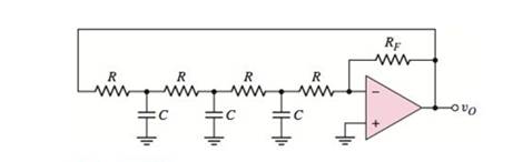
Consider the circuit shown below.

Calculation:
The non-inverting terminal of op-amp is grounded. Hence, the voltage
From virtual ground, the voltage at non-inverting terminal is equal to voltage at inverting terminal
Use KCL at the node
Use KCL at the node
Use KCL at the node
Substitute
Substitute equation (3) in equation (2),
Substitute equation (4) in equation (1),
Use KCL at the node
Substitute
Substitute
The transfer function is given by.
To find the frequency oscillation, set
From the Barkhausen criterion, the condition for oscillation is that
To satisfy the condition
Conclusion:
Therefore, the expression for the frequency of oscillation is
(b)
The condition of oscillation.
(b)
Answer to Problem 15.30P
The condition of oscillation is
Explanation of Solution
Given:
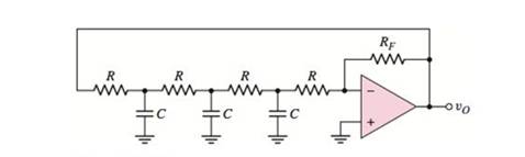
Consider the circuit shown below.
Calculation:
Substitute
The condition for oscillation is that
Substitute
Therefore, the required condition for oscillation is
Conclusion:
Therefore, the required expression for the frequency of oscillation is
(c)
To find: The values of capacitor and
(c)
Answer to Problem 15.30P
The required values are
Explanation of Solution
Given:
Consider the circuit shown below.
Calculation:
Substitute
Thus, the required feedback resistance is
Substitute
Conclusion:
Therefore, the required values are
Want to see more full solutions like this?
Chapter 15 Solutions
MICROELECT. CIRCUIT ANALYSIS&DESIGN (LL)


- 01) For the Oscillation circuit shown in Figure (1), derive an expression for the frequency of oscillation. RI/RO>>hie). Figure (1) VCC R1 Rc L1 Q3 R2 C2 SLI Rs Cs C1 ww Voarrow_forwardA chopper has input voltage of 290 and the load resistance as 50. the average load current as 50A. If the non-conducting time of thyristor chopper is 120 µ sec. Calculate the pulse width of output voltage in usec. In case pulse width is 1/3rd for constant frequency operation, find new output voltage. Duty Cycle pulse width of output voltage in sec new output voltagearrow_forwardIn a Wien bridge oscillator circuit, resistor and capacitor form a series branch and a parallel branch. The value of the resistor is 200 ohm and the value of the capacitor is 10 mF. Determine the frequency of oscillation for the Wien Bridge oscillator circuit.arrow_forward
- Draw a diagram for astable multivibrator using 555 timer. Find the oscillation frequency of the output signal and its duty cycle when the external capacitor is 0.01 uF, the R1 and R2 are 10 kn and 50 kn respectively. While the decoupling capacitor equal 0.1 µF. What happened to the duty cycle when R2 become 1M02?arrow_forwardA voltage commutated chopper operating at 1 kHz is used to control the speed of dc motor as shown in figure. The load current is assumed to be constant at 10 A. 00000 V = 250 V 1₁F XA vous 2mH The minimum time in uses for which the SCR M should be ON isarrow_forwardUsing two astable M.V timer .Desine the wave form shown in the figure below with Vcc=9v, C= 1.6234.Mf . then 1-Determine the duty cycle and the frequency at the output of each M.V timer 2- Draw Vc and Vo at each cct. output o/P 9.1 25 27 29.1 38.2 50 52 58.2 msarrow_forward
- A boost converter is required to have an output voltage of 8 V and supply a load current of 1 A. The input voltage varies from 2.7 to 4.2 V. A control circuit adjusts the duty ratio to keep the output voltage constant. Select the switching frequency. Determine a value for the inductor such that the variation in inductor current is no more than 40 percent of the average inductor current for all operating conditions. Determine a value of an ideal capacitor such that the output voltage ripple is no more than 2 percent. Determine the maximum capacitor equivalent series resistance for a 2 percent ripple.arrow_forward02 1) The PWM is new thechnigue adopted in power electronies application .explaine the advantages of this application 2) In Puls width modulation applieation we Use line and sine wave refrences .explane the advantages and dis advanteges each onearrow_forwardHome Work 1/ what js meant by Nyquí st rate ? Q2/ what s meant by Pulse Moduletim ? why we need PM?arrow_forward
- Boost Converter Design A boost converter is required to have an output voltage of 8 V and supply a load current of 1 A. The input voltage varies from 2.7 to 4.2 V. A control circuit adjusts the duty ratio to keep the output voltage constant. Select the switching frequency. Determine a value for the inductor such that the variation in inductor current is no more than 40 percent of the average inductor current for all operating conditions. Determine a value of an ideal capacitor such that the output voltage ripple is no more than 2 percent. Determine the maximum capacitor equivalent series resistance for a 2 percent ripple.arrow_forwardG) build a low-frequency square wave generator using a basic comparator having a frequency of 1kHz and a 30% duty cycle. Explain the principle of operation and the type of feedback of the op-amp. What is the advantage of this circuit? H) Build a phase-shift oscillator using, C=1µF and +10V power supply to produce a 10 kHz sinusoidal waveform. Generate your plots and compare output results. Highlight any discrepancies and discuss what happens if we want to increase the frequency to 100 kHz. I) Build a Colpitts oscillator producing 100kHz Discuss its advantage over RC oscillators. How can you modify the circuit to include a crystal in your circuit? What is a typical application of such an oscillator? Discuss the advantages and disadvantages of crystal oscillators.arrow_forwardA chopper has input voltage of 290 and the load resistance as 50, the average load current as 50A. If the non-conducting time of thyristor chopper is 120 Usec. Calculate the pulse width of output voltage in U sec. In case pulse width is 1/3rd for constant frequency operation, find new output voltage. Duty Cycle pulse width of output voltage in usec new output voltagearrow_forward
 Introductory Circuit Analysis (13th Edition)Electrical EngineeringISBN:9780133923605Author:Robert L. BoylestadPublisher:PEARSON
 Delmar's Standard Textbook Of ElectricityElectrical EngineeringISBN:9781337900348Author:Stephen L. HermanPublisher:Cengage Learning
 Programmable Logic ControllersElectrical EngineeringISBN:9780073373843Author:Frank D. PetruzellaPublisher:McGraw-Hill Education
 Fundamentals of Electric CircuitsElectrical EngineeringISBN:9780078028229Author:Charles K Alexander, Matthew SadikuPublisher:McGraw-Hill Education
 Electric Circuits. (11th Edition)Electrical EngineeringISBN:9780134746968Author:James W. Nilsson, Susan RiedelPublisher:PEARSON
 Engineering ElectromagneticsElectrical EngineeringISBN:9780078028151Author:Hayt, William H. (william Hart), Jr, BUCK, John A.Publisher:Mcgraw-hill Education,