
Videos
Find the sinusoidal expression for the voltage Ua for the system in Fig. 14.84 if
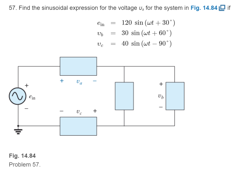
Fig. 14.84
Want to see the full answer?
Check out a sample textbook solution
Chapter 14 Solutions
Introductory Circuit Analysis (13th Edition)
Additional Engineering Textbook Solutions
Fundamentals of Electric Circuits
Loose Leaf for Engineering Circuit Analysis Format: Loose-leaf
Electronics Fundamentals: Circuits, Devices & Applications
Engineering Electromagnetics
Microelectronics: Circuit Analysis and Design
Principles Of Electric Circuits


- P.6: Find the sinusoidal expression for the current is for the system of Fig. 14.83 if i₁ = 6 x 10³ sin(377t + 180°) 1₂ = 8 x 10³ sin 377t 13 = 21₂ 15 FIG. 14.83 1₂arrow_forward1. When a 10 inductor and a 10 capacitor are connected in series, the impedance will be equal to: a. 0 b. infinity c. 10 d. 14.14arrow_forwardQuestions 16 to 20 (Write True or False) A16 A larger inductor produces a smaller rate of change of current. A17 KVL states that E IR + E EMF = 0 for any open circuits. A18 For a sine waveform, the value of form factor is 1.414. A19 In a purely inductive circuit, the current lags the voltage by II/4 rads. In an ideal transformer, the rate of change of flux is the same for both primary A20 and secondary.arrow_forward
- The RMS value of the voltage u(t)=3+4cos(3t) is ?arrow_forward9. A capacitor has a resistance of 80ohms when connected to a 50 Hz supply. Calculate the value of capacitance A. 39.79 microfarad B. 39.97 microfarad C. 93.79 microfarad D. 93.97 microfaradarrow_forwardCalculate the difference A B if A=10236.87 and B=10453.13°. Show your solution graphically.arrow_forward
- The voltage and current of an element are i(t) = 3.cos(1000t + 10°) V(t) = 6.cos(1000t – 80°) The element is Select one: a. resistor and capacitor (R and C) b. Сарacitor C c. resistor R d. Inductor Larrow_forwardInductance of the coil is given by O a. L= 10 / N O b. L= N|I O c. L= N® / O d. L= N0 / Tarrow_forward14:30 E P VS +23324657 2888 July 15, 14:03 EE 287 SINUSOIDAL STEADY STATE ANALYSIS ASSIGNMENT 3 1. Determine Vo in the circuit below 42 2H ww- 32 sin 4r V 4 cos 4r A HORTNE BREATH 2 Determinc lo in the circuit below using superposition principle 24 V 2 H ww 22 2 cos 3t 42 10 sin(t-30°) V()arrow_forward
- Solve the following for ALL circuits. Show the summary of your answers at the end of each problem. All answers should be in polar form! a. Total Current b. Individual Currents c. Individual Voltages d. True/Real power e. Reactive power f. Apparent power 1. Circuit 1 (freq=200 Hz) 10 K www 10 COSwt 100 100 LA HE 10 pFarrow_forward2- if y=sin(t), where ( -4 ≤ t ≤ 4) could you plot (t,y) as shown below: Figure 1 File Edit View Insert Tools Desktop Window Help 03 DE 33+ Graph of the sine function Y axis 1 0.8 0.6 0.4 0.2 0 -0.2 -0.4 -0.6 -0.8 -1 -3 -2 -1 0 X axis Sine function 1 2 3 4arrow_forwardInductive Circuits Fill in all the missing values. Refer to the following formulas: XL=2fLL=XL2ff=XL2L Inductance (H) Frequency (Hz) Inductive Reactance ( ) 1.2 60 0.085 213.628 1000 4712.389 0.65 600 3.6 678.584 25 411.459 0.5 60 0.85 6408.849 20 201.062 0.45 400 4.8 2412.743 1000 40.841arrow_forward
 Delmar's Standard Textbook Of ElectricityElectrical EngineeringISBN:9781337900348Author:Stephen L. HermanPublisher:Cengage Learning