
Introductory Circuit Analysis (13th Edition)
13th Edition
ISBN: 9780133923605
Author: Robert L. Boylestad
Publisher: PEARSON
expand_more
expand_more
format_list_bulleted
Videos
Textbook Question
Chapter 14, Problem 34P
In Fig. 14.79,
a. Find the sinusoidal expression for e.
b. Find the average power loss in the capacitor.
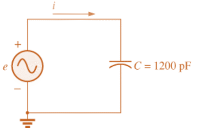
Fig. 14.79
Expert Solution & Answer
Want to see the full answer?
Check out a sample textbook solution
Students have asked these similar questions
P.6: Find the sinusoidal expression for the current is for the system of Fig.
14.83 if
i₁ = 6 x 10³ sin(377t + 180°)
1₂ = 8 x 10³ sin 377t
13 = 21₂
15
FIG. 14.83
1₂
The voltage applied to a purely inductive coil of self-inductance 15.9 mH is given by the equation v = 100 sin 314t + 75 sin 942t + 50 sm 1570t . Find the equation of the resulting current wave.
:D
A docs.google.com/forms/d/1 o
المرحلة والشعبة: *
A non-sinusoidal voltage
(e=20+15sin1000t+ 10sin3000t+5sin4000t)
Volt is applied to the circuit shown. Find the
?total power
iT 42
İL
-J92
J42
44.03 W
86.08 W
88.06 W
44.04 W
n-sinusoidal wave can be
طلب الإذن بالتعديل
of sine waves with
.harmonic frequencies
II
Chapter 14 Solutions
Introductory Circuit Analysis (13th Edition)
Ch. 14 - Plot the following waveform versus time showing...Ch. 14 - Repeat Problem 1 for the following sinusoidal...Ch. 14 - What is the derivative of each of the following...Ch. 14 - The voltage across a 20 resistor is as indicated....Ch. 14 - The current through a 6.8 k ) resistor is as...Ch. 14 - Determine the inductive reactance (in ohms) of a 2...Ch. 14 - Determine the closest standard value inductance...Ch. 14 - Determine the frequency at which a 47 mH...Ch. 14 - The current through a 20 inductive reactance is...Ch. 14 - The current through a 0.1 H coil is given. What is...
Ch. 14 - The voltage across a 40 inductive reactance is...Ch. 14 - The voltage across a 0.2 H coil is given. What is...Ch. 14 - Determine the capacitive reactance (in ohms) of a...Ch. 14 - Determine the closest standard value capacitance...Ch. 14 - Determine the frequency at which a 3.9 F capacitor...Ch. 14 - The voltage across a 2.5 capacitive reactance is...Ch. 14 - The voltage across a 1 F capacitor is given. What...Ch. 14 - The current through a 2 k capacitive reactance is...Ch. 14 - The current through a 0.56 F capacitor is given....Ch. 14 - For the following pairs of voltages and currents,...Ch. 14 - Repeat Problem 20 for the following pairs of...Ch. 14 - Plot XL versus frequency for a 3 mH coil using a...Ch. 14 - Plot XC versus frequency for a 1 F capacitor using...Ch. 14 - At what frequency will the reactance of a 1 F...Ch. 14 - The reactance of a coil equals the resistance of a...Ch. 14 - Determine the frequency at which a 1 F capacitor...Ch. 14 - Determine the capacitance required to establish a...Ch. 14 - Find the average power loss and power factor for...Ch. 14 - If the current through and voltage across an...Ch. 14 - A circuit dissipates 100 W (average power) at 150...Ch. 14 - The power factor of a circuit is 0.5 lagging. The...Ch. 14 - In Fig.14.77, e=120sin(260t+20). a. What is the...Ch. 14 - In Fig. 14.78, e=220sin(1000t+60). a. Find the...Ch. 14 - In Fig. 14.79, i=30103sin(2500t20). a. Find the...Ch. 14 - For the network in Fig. 14.80 and the applied...Ch. 14 - For the network in Fig. 14.81 and the applied...Ch. 14 - Convert the following from rectangular to polar...Ch. 14 - Convert the following from rectangular to polar...Ch. 14 - Convert the following from polar to rectangular...Ch. 14 - Convert the following from polar to rectangular...Ch. 14 - Perform the following additions in rectangular...Ch. 14 - Perform the following subtractions in rectangular...Ch. 14 - Perform the following operations with polar...Ch. 14 - Perform the following multiplications in...Ch. 14 - Perform the following multiplications in polar...Ch. 14 - Perform the following divisions in polar form:...Ch. 14 - Perform the following divisions, and leave the...Ch. 14 - Perform the following operations, and express your...Ch. 14 - Prob. 49PCh. 14 - Determine a solution for x and y if...Ch. 14 - Determine a solution for x and y if...Ch. 14 - Express the following in phasor from:...Ch. 14 - Express the following in phasor form:...Ch. 14 - Express the following phasor currents and voltages...Ch. 14 - For the system in Fig. 14.82, find the sinusoidal...Ch. 14 - For the system in Fig. 14.83 find the sinusoidal...Ch. 14 - Find the sinusoidal expression for the voltage Ua...Ch. 14 - Find the sinusoidal expression for the current i1...Ch. 14 - Plot icandUc versus time for the network in Fig....Ch. 14 - Plot the magnitude and phase angle of the current...Ch. 14 - Plot the total impedance of the configuration in...
Knowledge Booster


Learn more about
Need a deep-dive on the concept behind this application? Look no further. Learn more about this topic, electrical-engineering and related others by exploring similar questions and additional content below.Similar questions
- I) Convert the following phasors to the time domain if the frequency is I KHz. . h-3 A a) k- 12 /40 b)arrow_forwardGoogle Play A Maps YouTube Wolfram Alpha: Co.. E Padlet: You are bea. C++ Tutorial for Be. Other bookmarks Gmail Find the equivalent capacitance (in F) seen by the source if C = 8.5 F C C 4.15 O 2.07 O 1.04 3.11 Time left 1:13:00 11:02 AM E ENG P Type here to search 25°C 5/24/2021arrow_forward9. A capacitor has a resistance of 80ohms when connected to a 50 Hz supply. Calculate the value of capacitance A. 39.79 microfarad B. 39.97 microfarad C. 93.79 microfarad D. 93.97 microfaradarrow_forward
- For the resistor shown above what best describes its behavior at 1 MHz? It responds primarily as a resistor It responds primarily as a capacitor O It responds primarily as a inductor It responds primarily as a transformerarrow_forwardLP+ 3 17. The voltage across a 1 μF capacitor is given. What is the sinusoidal expression for the current? a. 30 sin 200t agon bast b. 60 x 10-3 sin 377tarrow_forwardQuestion 1 A series RLC circuit has a capacitor with a capacitance of 33.0 μF, an inductor with an inductance of 0.700 H and a resistor with a resistance of 114 Q. The circuit has a rms current of 6.30 A when the frequency is 95.0 Hz. What is the average power loss?arrow_forward
- LIsten In a purely capacitive circuit, the angular velocity (w) of the current is 377 rads/sec. The frequency of the power wave is: a) 60 Hz Øb) 377 Hz C) 120 Hz d) 3.60 kHz acerarrow_forward50. For the system in Fig. 14.87, find the sinusoidal expression for the unknown voltage vif = ein 60 sin(377t +20°) Ub = 20 sin(377t 20°) + Va FIG. 14.87 Problem 50. ein + Ubarrow_forwardThe voltage and current of an element are i(t) = 3.cos(1000t + 10°) V(t) = 6.cos(1000t – 80°) The element is Select one: a. resistor and capacitor (R and C) b. resistor R c. Inductor L d. Capacitor Carrow_forward
- QUESTION 3 An inductor, a capacitor, and a resistor are connected in series with a function generator. The inductor drops 5V RMS, the capacitor drops 20V RMS, and the resistor drops 2V RMS. Find the magnitude of the total voltage. O 27V RMS O 15V RMS O 38V RMS O 9V RMSarrow_forwardThe RMS value of the voltage u(t)=3+4cos(3t) is ?arrow_forward58. Two capacitors, a 20 µF and a 30 µF, are connected in series to a 60-Hz source. What is the total capacitive reactance? a. 117.96 N b. 221.04 N c. 253.05 N d. 333.16 Narrow_forward
arrow_back_ios
SEE MORE QUESTIONS
arrow_forward_ios
Recommended textbooks for you
 Introductory Circuit Analysis (13th Edition)Electrical EngineeringISBN:9780133923605Author:Robert L. BoylestadPublisher:PEARSON
 Delmar's Standard Textbook Of ElectricityElectrical EngineeringISBN:9781337900348Author:Stephen L. HermanPublisher:Cengage Learning
 Programmable Logic ControllersElectrical EngineeringISBN:9780073373843Author:Frank D. PetruzellaPublisher:McGraw-Hill Education
 Fundamentals of Electric CircuitsElectrical EngineeringISBN:9780078028229Author:Charles K Alexander, Matthew SadikuPublisher:McGraw-Hill Education
 Electric Circuits. (11th Edition)Electrical EngineeringISBN:9780134746968Author:James W. Nilsson, Susan RiedelPublisher:PEARSON
 Engineering ElectromagneticsElectrical EngineeringISBN:9780078028151Author:Hayt, William H. (william Hart), Jr, BUCK, John A.Publisher:Mcgraw-hill Education,
Introductory Circuit Analysis (13th Edition)
Electrical Engineering
ISBN:9780133923605
Author:Robert L. Boylestad
Publisher:PEARSON
Delmar's Standard Textbook Of Electricity
Electrical Engineering
ISBN:9781337900348
Author:Stephen L. Herman
Publisher:Cengage Learning
Programmable Logic Controllers
Electrical Engineering
ISBN:9780073373843
Author:Frank D. Petruzella
Publisher:McGraw-Hill Education
Fundamentals of Electric Circuits
Electrical Engineering
ISBN:9780078028229
Author:Charles K Alexander, Matthew Sadiku
Publisher:McGraw-Hill Education
Electric Circuits. (11th Edition)
Electrical Engineering
ISBN:9780134746968
Author:James W. Nilsson, Susan Riedel
Publisher:PEARSON
Engineering Electromagnetics
Electrical Engineering
ISBN:9780078028151
Author:Hayt, William H. (william Hart), Jr, BUCK, John A.
Publisher:Mcgraw-hill Education,
Inductors Explained - The basics how inductors work working principle; Author: The Engineering Mindset;https://www.youtube.com/watch?v=KSylo01n5FY;License: Standard Youtube License