
Videos
Plot the following waveform versus time showing one clear. Complete cycle. Then determine the derivative of the waveform using Eq. (14.1) and sketch one complete cycle of the derivative directly under the Original waveform. Compare the magnitude of the derivative at various points versus the slope of the original sinusoidal function.
To plot:
The graph of the waveform versus time for one complete cycle. Calculate the derivative of the waveform and then draw one complete cycle of it. Also, compare the magnitude of the derivative at various points versus the slope of the original sinusoidal function.
Explanation of Solution
Given:
The given equation is
Calculation:
Let us consider the sinusoidal expression of voltage as:
Standard sinusoidal equation is:
Comparing, we get
Value of frequency will be
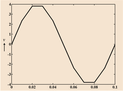
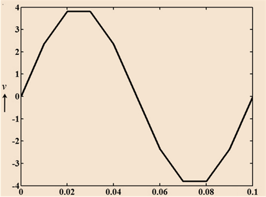
Voltage at
Voltage at
Voltage at
Voltage at
Voltage at
Voltage at
Graph showing voltage versus time
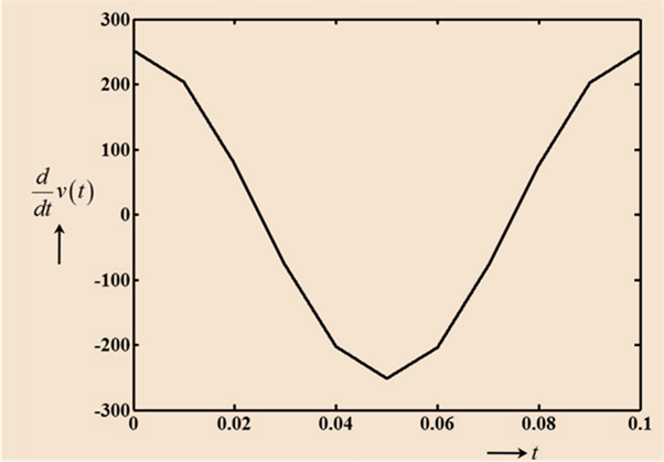
Derivative of standard sinusoidal equation is
Value of derivative of voltage at
Value of derivative of voltage at
Value of derivative of voltage at
Value of derivative of voltage at
Value of derivative of voltage at
Value of derivative of voltage at
Graph of derivative of voltage directly under the original waveform:
Want to see more full solutions like this?
Chapter 14 Solutions
Introductory Circuit Analysis (13th Edition)
Additional Engineering Textbook Solutions
Electrical Engineering: Principles & Applications (7th Edition)
Basic Engineering Circuit Analysis
Microelectronics: Circuit Analysis and Design
ELECTRICITY FOR TRADES (LOOSELEAF)
Engineering Electromagnetics
Fundamentals of Applied Electromagnetics (7th Edition)


- Please answer quickly The angular frequency of waveform having a period of 1 msec is 2pi radians/sec. True False Root mode square value of a signal is same as the effective value of a signal. True False The magnetic field energy stored in between the plates of the capacitor is mathematically equal to the half of the product of its capacitance and the square of the voltage across the capacitor. True Falsearrow_forwardConsider the sinusoids x1[n] = 2 sin(πn +2π/3) ,x2[n] = 3 cos(3πn + 3π/2) −∞ < n < ∞, From their frequencies determine if these signals are periodic, and if so, determine their corresponding periods.arrow_forwardIf V = 60V at α = 30° and t = 1.5 ms, determine the mathematical expression for the sinusodial voltagearrow_forward
- A circuit has an ac voltage source and a resistor and capacitorconnected in series. There is no inductor. The ac voltage source hasvoltage amplitude 900 V and angular frequency v = 20.0 rad/s. Thevoltage amplitude across the capacitor is 500 V. The resistor has resistanceR = 300 Ω. What is the average rate at which the ac source supplies electrical energy to the circuit?arrow_forward6. What is the sinusoidal expression of current through circuit contain only capacitor? (Where C=20μF, v=4 sin(1000t+20) Varrow_forwardfind the phase, frequency, amplitude, period of the sinusoid v(t) = 10sin(377t +45°). Graphically sketch the position of the sinusoidarrow_forward
- Question 1 a) You are a student of Accra Institute of Technology who is offering the course Signals and Systems. Would you classify a discrete-time sinusoidal signal as periodic or non-periodic? Give reasons for your answer. Support your answer with mathematical formulations if necessary.arrow_forwardGiven the applied signal and network below: a.) Determine the sinusoidal expressions for ?1 and ?2 b.) Find the sinusoidal expression is by combining the two parallel capacitors.arrow_forward49. The sinusoidal waveform is the fundamental type of waveform used in AC and is commercially distributed. True False 51. Peak factor of a signal is the ratio of the peak or maximum value to the RMS (root-median-square) value. True False 52. Periodic signals are signals that recur at a irregular time interval True Falsearrow_forward
- 1. solve equation of the sinusoidal signal v(t) from the information, where v(t) = Vp sin ωt. Vp-p = 6 div Oscilloscope setting: horizontal = 0.5 ms/div 1 cycle = 8 div vertical amplitude = 0.5 volt/div 2. 1 cycle of 2 sinusoidal signals displayed with 10 kHz on the oscilloscope screen. If the two signals have a difference time with 20µs, what the value of phase shift between two signals/waveforms displayed on the scope screen? 3. It is possible for a circuit made up of a resistor, an inductor, and a capacitor (connected in series or parallel) to behave like a purely resistive circuit. Explain why.arrow_forwardSolve for the steady state expression for vo(t) if vg(t) = 60 sin 8000t Varrow_forwardA 90 kHz sinusoidal voltage has zero phase angle and a maximum amplitude of 30 mV . When this voltage is applied across the terminals of a capacitor, the resulting steady-state current has a maximum amplitude of 629.60 μA . Pt A. What is the frequency of the current in radians per second? Pt B. What is the phase angle of the current? Pt C. What is the capacitive reactance of the capacitor?arrow_forward
 Introductory Circuit Analysis (13th Edition)Electrical EngineeringISBN:9780133923605Author:Robert L. BoylestadPublisher:PEARSON
 Delmar's Standard Textbook Of ElectricityElectrical EngineeringISBN:9781337900348Author:Stephen L. HermanPublisher:Cengage Learning
 Programmable Logic ControllersElectrical EngineeringISBN:9780073373843Author:Frank D. PetruzellaPublisher:McGraw-Hill Education
 Fundamentals of Electric CircuitsElectrical EngineeringISBN:9780078028229Author:Charles K Alexander, Matthew SadikuPublisher:McGraw-Hill Education
 Electric Circuits. (11th Edition)Electrical EngineeringISBN:9780134746968Author:James W. Nilsson, Susan RiedelPublisher:PEARSON
 Engineering ElectromagneticsElectrical EngineeringISBN:9780078028151Author:Hayt, William H. (william Hart), Jr, BUCK, John A.Publisher:Mcgraw-hill Education,