
Calculate the coupling coefficient of the circuit that make the
Answer to Problem 29P
The required coupling coefficient is
Explanation of Solution
Given data:
Refer to Figure 13.98 in the textbook for the circuit with coupled coils.
In Figure 13.98, consider that the primary and secondary loops contain the currents
The value of
The value of
Calculation:
Calculate the inductors in frequency domain.
Write the expression for the inductive reactance.
Substitute 30 mH for
Substitute 50 mH for
Consider that the value of X.
Substitute
Consider that the second side reflect on the primary side. Consider the expression for the input impedance.
Write the expression for the current
Substitute 330 V for V and Equation (3) in (4).
Consider the expression for the power dissipated in the
Substitute 1.288 kW for p.
Substitute 16 A for
Square on both sides of the equation.
Simplify the equation as follows.
By solving the above equation, there are two positive values of X and they are,
Consider that the value of X as 38.128.
Substitute 38.128 for X in Equation (2).
Consider the expression for the coefficient of coupling in the coupled coils.
Substitute 38.128 mH for M, 30 mH for
Modify the Figure 13.98 by transforming the time-domain circuit with coupled-coils to frequency domain of the circuit with coupled-coils. The frequency domain equivalent circuit is shown in Figure 1.
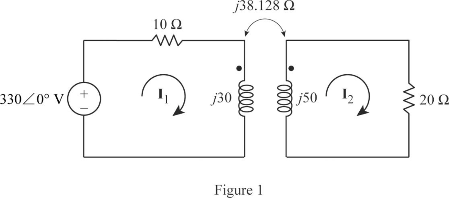
From Figure 1, consider that the loops 1 and 2 contain the currents
Apply Kirchhoff's voltage law to the loop 1 in Figure 1.
Apply Kirchhoff's voltage law to the loop 2 in Figure 1.
Write equations (6) and (7) in matrix form as follows.
Write the MATLAB code to solve the equation (8).
A = [(10+j*30) j*(-38.128); j*(-38.128) (20+j*50)];
B = [330; 0];
I = inv(A)*B
The output in command window:
I =
15.535 - 3.829i
11.219 + 1.568i
From the MATLAB output, the currents
And
Write the currents
Substitute 1.5 ms for t in Equation (9).
Substitute 1.5 ms for t in Equation (10).
Write the expression for the total energy stored in the coupled coils.
Substitute 30 mH for
Conclusion:
Thus, the required coupling coefficient is
Want to see more full solutions like this?
Chapter 13 Solutions
EBK FUNDAMENTALS OF ELECTRIC CIRCUITS

- When an impedance coil is connected to a 100 V, 60-Hz, ac supply, the circuit current is 1 A. When it is connected to a 100 V, 30-Hz, ac supply, the circuit current is 1.38675 A. Find the resistance and the inductance of the impedance coil.arrow_forwardA coil of resistance 50 ohm and 0.318H is connected in parallel with a circuit comprising a 75 ohm resistor in series with a 159 micro-farad capacitor. The resulting circuit is connected to a 230V, 50Hz ac supply. Determine the supply current, and all the branch currents.arrow_forwardan AC motor is connected to a 560 V 60 HZ line the motor has a current draw at full load of 53 Amps and a true power of 18700 W whats the power factor of the motor and find the amount of capacitance that should be connected in parallel with the motor to correct the power factor to 100% or unity.arrow_forward
- (Basic Electrical Engineering) A series circuit consisting of a 13-ohm resistor, 0.05 H inductor and a 10-microfarad capacitor is connected across a 100V. Determine the frequency of the supply if the current flowing is 5A. Show complete solution and limit your answer jnto three decimal places.arrow_forwardQ3: A three stage Cockroft-Walton generator is supplied by 212.133 V, 50 Hz source via a transformer with turns ratio equals to 2/800. All capacitors have a value of (0.8 µF). The protection current equals to 15 mA. Find the following: a. Find the output peak voltage that is used for testing without considering the voltage drop. b. Find the output peak voltage that is used for testing with considering the voltage drop. c. What is the ripple voltage? d. If the lowest capacitor is increased to twice its value, what is the output peak voltage that is used for testing with considering the voltage drop. e. Comparing the results of ( b ) and ( d ) above , do you recommend doubling the value of the lowest capacitor or not? f. According to the circuit values, is the 3 stages represents the optimum number of stages for this generator?arrow_forwardA coil has an inductance of 39.8 microH and a series resistance of 20 ohms. Find its impedance at a frequency of 100 kHz and the current through the circuit if the voltage drop across the circuit is 80 V. Also find the voltage drop across the resistor u the voltage drop across the coil .arrow_forward
- Two coils are A and B are connected in series to a supply of 230V, 50HZ. Coil A has an inductance of 0.2H and a resistance of 20 Q, and coil B has an inductance of 0.05H and a resistance of 60 Q. Calculate the current and its phase angle relative to the supply voltage. Also determine the voltage across each coil.arrow_forwardTwo coupled coils of L1=0.8 H and L2=0.2 H have a coupling coefficient K=0.8. What will their mutual inductance ?arrow_forward1- In a buck DC/DC converter: ton V₁ = 100 V, R= 80, D ==0.8, f == 20000 Hz, L = 200 μH, Find: a) average voltage and current of the load Vala. b) maximum and minimum current of inductor. c) Voltage ripple of the capacitor. d) the average input current. e) draw the figure of the inductor current. C1 = 40 Micro farad Q Vd - İd K C1 ww + Voarrow_forward
- 1. A coil has a resistance of 18 ohm when its mean temperature is 20 °C and of 20 ohm when its mean temperature is 50°C . Find the mean temperature rise when its resistance is 21 ohm and the surroundings isn15 °C.arrow_forward11. Two coupled coils have self-inductances L1 = 2 H and L2 = 0.5 H, and a coefficient of coupling K = 0.9. Determine the turns ratio N1/N2 of the two coils. a. 2 b. 0.2 c. 0.5 d. 0.9arrow_forwardA coil has inductance of 5 H and resistance 20 ohms and voltage connected of 100 volt battery. Find energy stored into the coil.arrow_forward
 Introductory Circuit Analysis (13th Edition)Electrical EngineeringISBN:9780133923605Author:Robert L. BoylestadPublisher:PEARSON
 Delmar's Standard Textbook Of ElectricityElectrical EngineeringISBN:9781337900348Author:Stephen L. HermanPublisher:Cengage Learning
 Programmable Logic ControllersElectrical EngineeringISBN:9780073373843Author:Frank D. PetruzellaPublisher:McGraw-Hill Education
 Fundamentals of Electric CircuitsElectrical EngineeringISBN:9780078028229Author:Charles K Alexander, Matthew SadikuPublisher:McGraw-Hill Education
 Electric Circuits. (11th Edition)Electrical EngineeringISBN:9780134746968Author:James W. Nilsson, Susan RiedelPublisher:PEARSON
 Engineering ElectromagneticsElectrical EngineeringISBN:9780078028151Author:Hayt, William H. (william Hart), Jr, BUCK, John A.Publisher:Mcgraw-hill Education,