
Videos
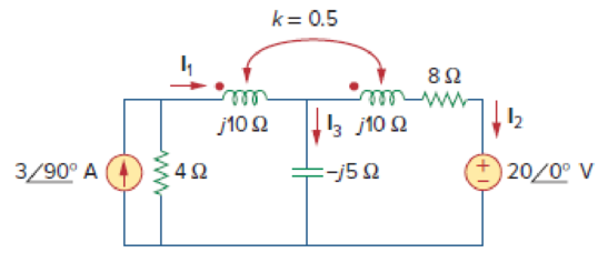
Determine currents I1, I2, and I3 in the circuit of Fig. 13.89. Find the energy stored in the coupled coils at t = 2 ms. Take ω = 1,000 rad/s.
Calculate the currents
Answer to Problem 20P
The currents
Explanation of Solution
Given data:
Refer to Figure 13.89 in the textbook for the circuit with coupled coils.
The value of
Calculation:
Calculate the mutual inductance in frequency domain.
Modify the Figure 13.89 by transforming the current source
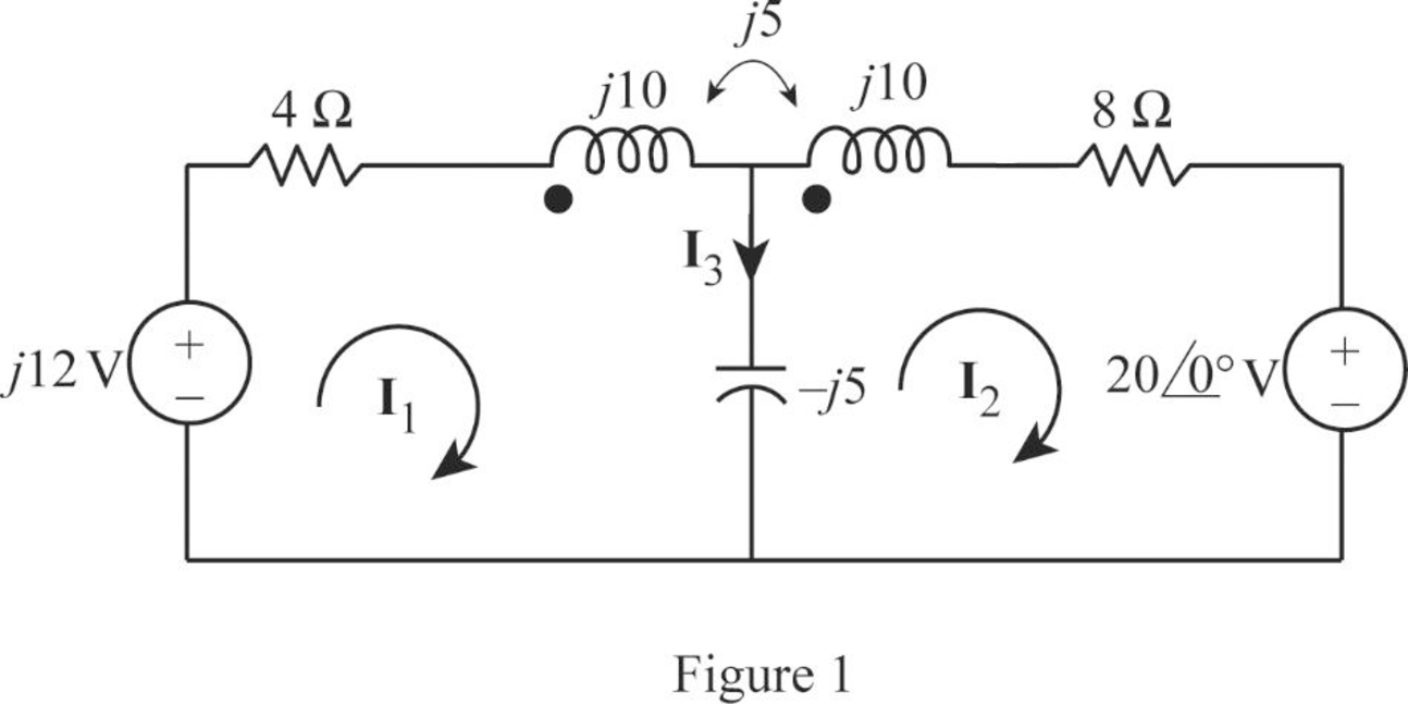
From Figure 1, consider that the loops 1 and 2 contain the currents
Apply Kirchhoff's voltage law to the loop 1 in Figure 1.
Apply Kirchhoff's voltage law to the loop 2 in Figure 1.
Write equations (1) and (2) in matrix form as follows.
Write the MATLAB code to solve the equation (3).
A = [(4+j*5) j*10;j*10 (8+j*5)];
B = [j*12; -20];
C = inv(A)*B
The output in command window:
C =
0.75354 + 2.34381i
-0.11429 - 0.87049i
From the MATLAB output, the currents
And
From Figure 1, consider the expression for the current
Substitute
Write the current
Substitute 2 ms for t in Equation (4).
Substitute 2 ms for t in Equation (5).
From Figure 13.81, find the inductor values.
Calculate the inductor
Substitute 1000 for
Calculate the inductor
Substitute 1000 for
And
Calculate the mutual inductance.
Substitute 0.01 H for
Write the expression for the total energy stored in the coupled coils.
Substitute 0.01 H for
Conclusion:
Thus, the currents
Want to see more full solutions like this?
Chapter 13 Solutions
EBK FUNDAMENTALS OF ELECTRIC CIRCUITS


- A coil has resistance of 5 ohm and inductive reactance of 4 ohm. a) what is the impedance of the coil? b) what is the admittance of the coil?arrow_forwardA coil has an inductance of 39.8 microH and a series resistance of 20 ohms. Find its impedance at a frequency of 100 kHz and the current through the circuit if the voltage drop across the circuit is 80 V. Also find the voltage drop across the resistor u the voltage drop across the coil .arrow_forwardThe impedance coil absorbs 250 watts when connected across 220 V, 60 Hz mains, it is then connected across 110 V, 25 Hz mains and also absorbs 250 watts. What is the inductance of the coil? Show complete solution.arrow_forward
- 11. Two coupled coils have self-inductances L1 = 2 Hand L2 = 0.5 H, and a coefficient of coupling K = 0.9. Determine the turns ratio N1/N2 of the two coils. ww w а. 2 b. 0.2 c. 0.5 d. 0.9arrow_forwardAn impedance coil draws 100 VA, 80 W. Solve for the power-factor of the coil.arrow_forwardA coil has a resistance of 10 ohms and draws a current of 5A when connected across a 100-V, 60 Hz source. Determine A) the inductance in the coil, B) the power factor of the circuit and C) the reactive power. Answers: A) 45.94 mH, B) 0.5 lagging, C) 433 VARarrow_forward
- 1. A coil has a resistance of 18 ohm when its mean temperature is 20 °C and of 20 ohm when its mean temperature is 50°C . Find the mean temperature rise when its resistance is 21 ohm and the surroundings isn15 °C.arrow_forwardPLEASE SHOW COMPLETE SOLUTION In a laboratory experiment, the impedance of a coil was obtained at 60 Hz and 30 Hz. These are 75.48 ohms and 57.44 ohms, respectively. What is the resistance of the coil? 50 Ohms 80 Ohm 60 Ohms 70 Ohmsarrow_forwardA coil of inductance 159.2mH and resistance 20ohms is connected in series with a 60ohms resistor to a 240V, 50HZ supply. Determine a) the impedance of the circuit, b) the current in the circuit, c) the circuit phase angle, d) the p.d. difference across the resistor and the coil, e) draw the circuit phasor diagram showing all voltages.arrow_forward
- 11. Two coupled coils have self-inductances L1 = 2 H and L2 = 0.5 H, and a coefficient of coupling K = 0.9. Determine the turns ratio N1/N2 of the two coils. a. 2 b. 0.2 c. 0.5 d. 0.9arrow_forwardWhat is the impedance of a transformer coil that has 340' of #18 copper wire and an inductance of 70mH at 60Hz? 1000’ of #18 copper wire is 16 ohms.arrow_forwardThe mutual inductance between two coupled coil is 25 mH. If the turns in one coils are doubled and that in the other are halved, then the mutual inductance will become Take (k=1) Ideal condition.arrow_forward
 Introductory Circuit Analysis (13th Edition)Electrical EngineeringISBN:9780133923605Author:Robert L. BoylestadPublisher:PEARSON
 Delmar's Standard Textbook Of ElectricityElectrical EngineeringISBN:9781337900348Author:Stephen L. HermanPublisher:Cengage Learning
 Programmable Logic ControllersElectrical EngineeringISBN:9780073373843Author:Frank D. PetruzellaPublisher:McGraw-Hill Education
 Fundamentals of Electric CircuitsElectrical EngineeringISBN:9780078028229Author:Charles K Alexander, Matthew SadikuPublisher:McGraw-Hill Education
 Electric Circuits. (11th Edition)Electrical EngineeringISBN:9780134746968Author:James W. Nilsson, Susan RiedelPublisher:PEARSON
 Engineering ElectromagneticsElectrical EngineeringISBN:9780078028151Author:Hayt, William H. (william Hart), Jr, BUCK, John A.Publisher:Mcgraw-hill Education,