
Concept explainers
Videos
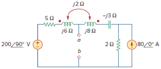
Obtain the Thevenin equivalent circuit for the circuit in Fig. 13.83 at terminals a-b.
Calculate the Thevenin equivalent to the circuit at terminals a-b.
Answer to Problem 14P
TheThevenin equivalent circuit parameters are
Explanation of Solution
Given data:
Refer to Figure 13.83 in the textbook for the circuit with coupled coils.
Consider that the value of the source voltage.
Calculation:
Calculate the Thevenin voltage.
Modify the Figure 13.83 by converting the current source
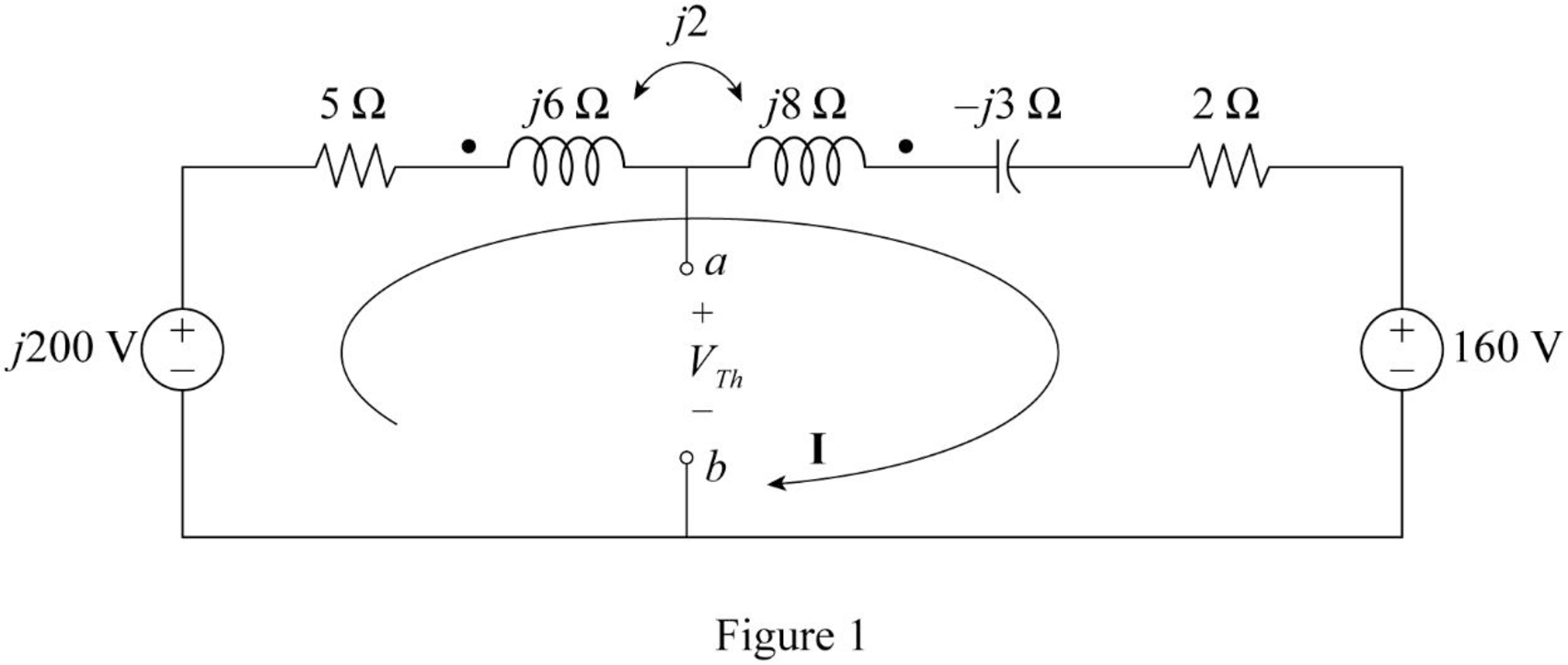
Consider that the two coils are connected series aiding.
Substitute
Apply Kirchhoff's voltage law to the loop 1 contains current
Substitute
Re-arrange the equation.
From Figure 1, consider the following expression using Kirchhoff's voltage law.
Re-arrange the Equation.
Substitute Equation (1) in (2).
Simplify the equation as follows.
To obtain Thevenin impedance
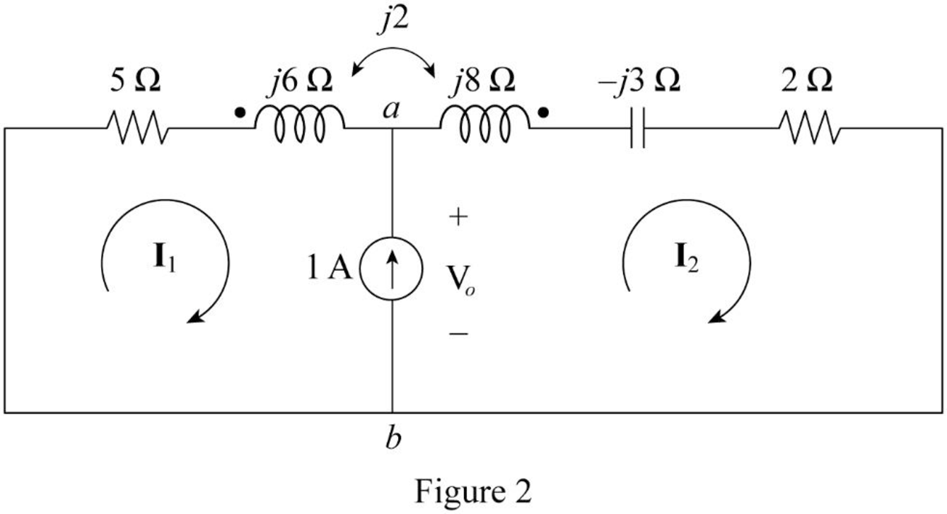
In Figure 2, consider that the loops 1 and 2 contain the currents
Write the Kirchhoff's voltage law expression to Figure 2 using super mesh analysis.
From Figure 2, write the current expression.
Substitute
Apply Kirchhoff's voltage law to the loop 1 contains current
Re-arrange the equation.
Substitute Equation (4) in (5).
Write the expression for Thevenin’s equivalent impedance.
Substitute
Conclusion:
Thus, the Thevenin equivalent circuit parameters are
Want to see more full solutions like this?
Chapter 13 Solutions
EBK FUNDAMENTALS OF ELECTRIC CIRCUITS
Additional Engineering Textbook Solutions
Principles Of Electric Circuits
ANALYSIS+DESIGN OF LINEAR CIRCUITS(LL)
Principles and Applications of Electrical Engineering
Electrical Engineering: Principles & Applications (7th Edition)
Loose Leaf for Engineering Circuit Analysis Format: Loose-leaf
Electronics Fundamentals: Circuits, Devices & Applications


- An engineer simplifies the circuit as follows. Do you agree? Explain.arrow_forward6) Compare between the results obtained by practical and Multisim ones.arrow_forwardfor the circuit shown below If v_in=5 sin2m10t then corner frequency will be ......Hz 1 UF 2 k Ohm 1 k Ohim 050 060 070 080 vinarrow_forward
- AC Circuits- Determine the Thevenin Equivalent Circuit with respect to terminal A and B. Pls show full and clean solution thank you.arrow_forwardA coil which has an equivalent impedance of 80∟30 is in series with a capacitor of 450 microfarad. The combination is in parallel with another coil which has a resistance and reactance of 35 ohms and 53 ohms respectively. What is the total impedance of the whole circuit? Frequency of 60Hzarrow_forwardA thyristor carries a current as shown below. The current pulse is repeated at a frequency of f=1 kHz. The average on-state current I- is then: i(A) 1000 0. 5 us 5 ps Select one: O a. 555A O b. 775A Oc. 335A Od. 995A TOSHIBAarrow_forward
- ZVO A VM ll l Ciassroo docs.google.com a Q1 For the following circuit diagram, 1 is .......... 50 15 V 12V 40 50 I2 70 60 90 12 a 4 A 1 O -1 احمد عصام احمد 8:00- äc lul 21.04.20 O Darrow_forwardThe parameter of a Certain linear transformer are R1=4000 R2: 300 e, Li=8H The trans formmer Couples an impedance cons 5000 esistor in series with a 7 HF Capacifor to a Sinusoidal voltage Source The 4ooV(xms) Source has an internal inmpedance af Prequency of 200 Yad/s Calculate the Self impedance of the primary auel Seconday Circuits, auel Calculate impedance reflected into the primary windiag and Calculate the scaling Factor for the reflecteef impedance and Catculate the impedance Seen loakiag into the primary terminals of the trans former auat Calculate the Thevenia 2 avel (3) 2:6H,k=0.9 sistingof an 3004il00.e and equivalent with respect to the feminolsarrow_forwardIn any circuit if we have AC and DC sources, then circuit must be analyzed by superposition Select one: True Falsearrow_forward
- The circuit below is powered by 230v 50hz network voltage R=50ohm Transformer conversion rate 1:1 Cutting angle 60 Effective value of output voltage?arrow_forward12. Two identical coupled coils have an equivalent inductance of 100 mH when connected series aiding and 50 mH in series opposing. What are the values of the self-inductance L1 and L2? a. 3.75 mH www www b. 375 mH c. 0.375 mH d. 37.50 mH ww ww wwarrow_forwardUse the figure to design a problem that helps other students to better understand nodal analysis.arrow_forward
 Introductory Circuit Analysis (13th Edition)Electrical EngineeringISBN:9780133923605Author:Robert L. BoylestadPublisher:PEARSON
 Delmar's Standard Textbook Of ElectricityElectrical EngineeringISBN:9781337900348Author:Stephen L. HermanPublisher:Cengage Learning
 Programmable Logic ControllersElectrical EngineeringISBN:9780073373843Author:Frank D. PetruzellaPublisher:McGraw-Hill Education
 Fundamentals of Electric CircuitsElectrical EngineeringISBN:9780078028229Author:Charles K Alexander, Matthew SadikuPublisher:McGraw-Hill Education
 Electric Circuits. (11th Edition)Electrical EngineeringISBN:9780134746968Author:James W. Nilsson, Susan RiedelPublisher:PEARSON
 Engineering ElectromagneticsElectrical EngineeringISBN:9780078028151Author:Hayt, William H. (william Hart), Jr, BUCK, John A.Publisher:Mcgraw-hill Education,