
Engineering Electromagnetics
9th Edition
ISBN: 9780078028151
Author: Hayt, William H. (william Hart), Jr, BUCK, John A.
Publisher: Mcgraw-hill Education,
expand_more
expand_more
format_list_bulleted
Videos
Textbook Question
Chapter 13, Problem 13.29P
An asymmetric slab waveguide is shown in Figure 13.26. In this case, the regions above and below the slab have unequal refractive indices, where n1 > n3 > n2. (a) Write, in terms of the appropriate indices, an expression for the minimum possible wave angle, 81, that a guided mode may have. (b) Write an expression for the maximum phase velocity a guided mode may have m this structure, using given, or known parameters.
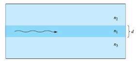
Figure 13.26 See Problem 13.29.
Expert Solution & Answer
Want to see the full answer?
Check out a sample textbook solution
Students have asked these similar questions
What is field pattern in a. Rectangular waveguide?b. TE mode in rectangular waveguide?c. TM mode in rectangular waveguide?
P 2.7a
What will be the cutoff wavelength for dominant mode in rectangular
waveguide whose length is 10 cm?
(2)
A 2 V signal is incident to the interface from a 75 Ohm region propagating to a 50 Ohm impedance region. What is the reflection coefficient? What is value of the incident, reflected and transmitted wave? What voltage would you measure on either side of the interface right after the signal goes through the interface.
Chapter 13 Solutions
Engineering Electromagnetics
Ch. 13 - The conductors of a coaxial transmission line are...Ch. 13 - Prob. 13.2PCh. 13 - Prob. 13.3PCh. 13 - Find R, L, C, and G for a two-wire transmission...Ch. 13 - Prob. 13.5PCh. 13 - Consider an air-filled coaxial transmission line...Ch. 13 - Pertinent dimensions for the transmission line...Ch. 13 - A transmission line constructed from perfect...Ch. 13 - Prob. 13.9PCh. 13 - Two microstrip lines are fabricated end-to-end on...
Ch. 13 - Prob. 13.11PCh. 13 - Prob. 13.12PCh. 13 - Prob. 13.13PCh. 13 - Prob. 13.14PCh. 13 - For the guide of Problem 13.14, and at the 32 GHz...Ch. 13 - Prob. 13.16PCh. 13 - A parallel-plate guide is partially filled with...Ch. 13 - Prob. 13.18PCh. 13 - Prob. 13.19PCh. 13 - Two rectangular waveguides are joined end-to-end....Ch. 13 - Prob. 13.21PCh. 13 - Consider the TE11 mode in a rectangular guide...Ch. 13 - Prob. 13.23PCh. 13 - Prob. 13.24PCh. 13 - Prob. 13.25PCh. 13 - Prob. 13.26PCh. 13 - Prob. 13.27PCh. 13 - Prob. 13.28PCh. 13 - An asymmetric slab waveguide is shown in Figure...Ch. 13 - A step index optical fiber is known to be single...Ch. 13 - Prob. 13.31PCh. 13 - Prob. 13.32P
Knowledge Booster


Learn more about
Need a deep-dive on the concept behind this application? Look no further. Learn more about this topic, electrical-engineering and related others by exploring similar questions and additional content below.Similar questions
- A 2 V signal is incident to the interface from a 75 Ohm region propagating to a 50 Ohm impedance region. What is the reflection coefficient? What is value of the incident, reflected and transmitted wave? What voltage would you measure on either side of the interface right after the signal goes through the interface. For the interface, I'm a little confused. I used a voltage divider and got V_transmitted = 0.8 and V_incident = 1.2. But shouldn't they be the same?arrow_forwardWhat does the TE mean? Why does one have a 10 as subscript and the other mn? What is a broad and short dimension and a rectangular waveguide?arrow_forwardA single mode fibre is to be dimensioned. The normalised frequency is 80 % of the maximum allowed for single mode condition. The relative refractive index difference is 0.005 and the refractive index of the core is 1.5. The wavelength is 1.5 µm. A. Determine the radius of the core. B. If the number of modes supported by this fiber is 5. Determine the radius of the core.arrow_forward
- 3) Solve the cutoff frequency for the first mode and third mode of WR137 waveguide. TABLE 7.1 Some Standard Rectangular Waveguides Waveguide designation a (in) b (in) t (in) Seo (GHz) Frequency range (GHz) WR975 9.750 4.875 0.125 0.605 0.75-1.12 WR650 6.500 3.250 0.080 0.908 1.12-1.70 WR430 4.300 2.150 0.080 1.375 1.70-2.60 WR284 2.840 1.340 0.080 2.08 2.60-3.95 WR187 1.872 0.872 0.064 3.16 3.95-5.85 WR137 1.372 0.622 0.064 4.29 5.85-8.20 WR90 0.900 0.450 0.050 6.56 8.2-12.4 WR62 0.622 0.311 0.040 9.49 12.4-18arrow_forwardQ2: Explain the reason(s) for the following: ZIT JEON TE 1. Why in TE mode both m and n can't be equal to zero? 2. TEM mode not propagate in the rectangular wave guide? 3. TE10 is the dominate mode in the rectangular wave guide? 4. There is no TE10 and TM₁0 modes in circular waveguide? 5. Quasi TEM modes propagates in the slot line or coplanar waveguide only?arrow_forwardWhat are em and he modes? How do they differ from te and tem modes? What is a single mode waveguide and why is it 0th order mode?arrow_forward
- 3.9 Explain what is meant by the critical bending radius for an optical fiber. A multimode graded index fiber has a refractive index at the core axis of 1.46 with a cladding refractive index of 1.45. The critical radius of curvature which allows large bending losses to occur is 84 um when the fiber is transmitting light of a particular wavelength. Determine the wavelength of the transmitted light. Ans: 0.86 µmarrow_forwardThis question from micorowave system course.arrow_forwardFigure: structure of a thin film silicon solar cell. Glass Front ITO i (aSi:H) back ZnO:AI 1-D PC The figure above shows a schematic overview of an thin film single junction solar cell. Upon what principle is the back reflector of this solar cell based? The principle of the back reflector is based on refractive scattering. ) The principle of the back reflector is based on diffractive scattering. ) The principle of the back reflector is based on constructive/destructive interference. The principle of the back reflector is based on plasmonic scatteringarrow_forward
- Electrical Engineering 1a.) What electric and magnetic fields correspond to the TM modes of a 1D ideal metallic waveguide? 1b.) What wave equation or wave equations apply to the TM modes? 1c.) How do you describe a TM plane wave bouncing between the two infinite metallic sheets? 1d.) What wave equation are you solving for the TM modes?arrow_forwardQ5 a) A fiber has the following characteristics: n1 = 1.45 (core index) and A=2%. Find the N.A and the acceptance angle.arrow_forward3.17 Consider the grounded magnetic substrate shown in the accompanying figure. Derive a solution for the TM surface waves that can propagate on this structure.arrow_forward
arrow_back_ios
SEE MORE QUESTIONS
arrow_forward_ios
Recommended textbooks for you
 Introductory Circuit Analysis (13th Edition)Electrical EngineeringISBN:9780133923605Author:Robert L. BoylestadPublisher:PEARSON
 Delmar's Standard Textbook Of ElectricityElectrical EngineeringISBN:9781337900348Author:Stephen L. HermanPublisher:Cengage Learning
 Programmable Logic ControllersElectrical EngineeringISBN:9780073373843Author:Frank D. PetruzellaPublisher:McGraw-Hill Education
 Fundamentals of Electric CircuitsElectrical EngineeringISBN:9780078028229Author:Charles K Alexander, Matthew SadikuPublisher:McGraw-Hill Education
 Electric Circuits. (11th Edition)Electrical EngineeringISBN:9780134746968Author:James W. Nilsson, Susan RiedelPublisher:PEARSON
 Engineering ElectromagneticsElectrical EngineeringISBN:9780078028151Author:Hayt, William H. (william Hart), Jr, BUCK, John A.Publisher:Mcgraw-hill Education,
Introductory Circuit Analysis (13th Edition)
Electrical Engineering
ISBN:9780133923605
Author:Robert L. Boylestad
Publisher:PEARSON
Delmar's Standard Textbook Of Electricity
Electrical Engineering
ISBN:9781337900348
Author:Stephen L. Herman
Publisher:Cengage Learning
Programmable Logic Controllers
Electrical Engineering
ISBN:9780073373843
Author:Frank D. Petruzella
Publisher:McGraw-Hill Education
Fundamentals of Electric Circuits
Electrical Engineering
ISBN:9780078028229
Author:Charles K Alexander, Matthew Sadiku
Publisher:McGraw-Hill Education
Electric Circuits. (11th Edition)
Electrical Engineering
ISBN:9780134746968
Author:James W. Nilsson, Susan Riedel
Publisher:PEARSON
Engineering Electromagnetics
Electrical Engineering
ISBN:9780078028151
Author:Hayt, William H. (william Hart), Jr, BUCK, John A.
Publisher:Mcgraw-hill Education,
FM and Phase Modulation Explained in Xfer's SERUM; Author: Ghosthack;https://www.youtube.com/watch?v=A2q2MpeVtXU;License: Standard Youtube License