
Engineering Electromagnetics
9th Edition
ISBN: 9780078028151
Author: Hayt, William H. (william Hart), Jr, BUCK, John A.
Publisher: Mcgraw-hill Education,
expand_more
expand_more
format_list_bulleted
Concept explainers
Videos
Textbook Question
Chapter 13, Problem 13.17P
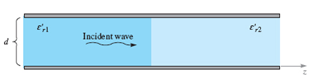
A parallel-plate guide is partially filled with two lossless dielectrics (Figure 13.25) where er1'=4.0, Er2'=2.1, and d= 1 cm. At a certain frequency, it is Found that the TM1 mode propagates through the guide without suffering any reflective loss at the dielectric interface, (a) Find this frequency. (b) Is the guide operating at a single TM mode at the frequency found in part a? Hint. Remember Brewster’s angle?
Expert Solution & Answer
Want to see the full answer?
Check out a sample textbook solution
Students have asked these similar questions
A 2 V signal is incident to the interface from a 75 Ohm region propagating to a 50 Ohm impedance region. What is the reflection coefficient? What is value of the incident, reflected and transmitted wave? What voltage would you measure on either side of the interface right after the signal goes through the interface.
For the interface, I'm a little confused. I used a voltage divider and got V_transmitted = 0.8 and V_incident = 1.2. But shouldn't they be the same?
What is field pattern in a. Rectangular waveguide?b. TE mode in rectangular waveguide?c. TM mode in rectangular waveguide?
What does the TE mean? Why does one have a 10 as subscript and the other mn? What is a broad and short dimension and a rectangular waveguide?
Chapter 13 Solutions
Engineering Electromagnetics
Ch. 13 - The conductors of a coaxial transmission line are...Ch. 13 - Prob. 13.2PCh. 13 - Prob. 13.3PCh. 13 - Find R, L, C, and G for a two-wire transmission...Ch. 13 - Prob. 13.5PCh. 13 - Consider an air-filled coaxial transmission line...Ch. 13 - Pertinent dimensions for the transmission line...Ch. 13 - A transmission line constructed from perfect...Ch. 13 - Prob. 13.9PCh. 13 - Two microstrip lines are fabricated end-to-end on...
Ch. 13 - Prob. 13.11PCh. 13 - Prob. 13.12PCh. 13 - Prob. 13.13PCh. 13 - Prob. 13.14PCh. 13 - For the guide of Problem 13.14, and at the 32 GHz...Ch. 13 - Prob. 13.16PCh. 13 - A parallel-plate guide is partially filled with...Ch. 13 - Prob. 13.18PCh. 13 - Prob. 13.19PCh. 13 - Two rectangular waveguides are joined end-to-end....Ch. 13 - Prob. 13.21PCh. 13 - Consider the TE11 mode in a rectangular guide...Ch. 13 - Prob. 13.23PCh. 13 - Prob. 13.24PCh. 13 - Prob. 13.25PCh. 13 - Prob. 13.26PCh. 13 - Prob. 13.27PCh. 13 - Prob. 13.28PCh. 13 - An asymmetric slab waveguide is shown in Figure...Ch. 13 - A step index optical fiber is known to be single...Ch. 13 - Prob. 13.31PCh. 13 - Prob. 13.32P
Knowledge Booster


Learn more about
Need a deep-dive on the concept behind this application? Look no further. Learn more about this topic, electrical-engineering and related others by exploring similar questions and additional content below.Similar questions
- 9 What is field pattern in m.)TE mode in rectangular waveguide?n.)TM mode in rectangular waveguide?arrow_forwardWhat are em and he modes? How do they differ from te and tem modes? What is a single mode waveguide and why is it 0th order mode?arrow_forwardFigure: structure of a thin film silicon solar cell. Glass Front ITO i (aSi:H) back ZnO:AI 1-D PC The figure above shows a schematic overview of an thin film single junction solar cell. Upon what principle is the back reflector of this solar cell based? The principle of the back reflector is based on refractive scattering. ) The principle of the back reflector is based on diffractive scattering. ) The principle of the back reflector is based on constructive/destructive interference. The principle of the back reflector is based on plasmonic scatteringarrow_forward
- 3) Solve the cutoff frequency for the first mode and second mode of WR975 Wave guide TABLE 7.1 Some Standard Rectangular Waveguides Waveguide de signation a (in) b (in) t (in) fe, (GHz) Frequency range (GHz) WR975 9.750 4.875 0.125 0.605 0.75-1.12 WR650 6.500 3.250 0.080 0.908 1.12–1.70 WR430 4.300 2.150 0.080 1.375 1.70-2.60 WR284 2.840 1.340 0.080 2.08 2.60-3.95 WR187 1.872 0.872 0.064 3.16 3.95-5.85 WR137 1.372 0.622 0.064 4.29 5.85-8.20 WR90 0.900 0.450 0.050 6.56 8.2–12.4 WR62 0.622 0.311 0.040 9.49 12.4–18arrow_forwardA 2.28-cm by 1.01-cm waveguide is filled with a dielectric material with er = 2.25. The waveguideoperate at 15GHZ. For TE11 and TE02 mode which mode will propagete.arrow_forwarda) Define Guide wavelength with the formula? b) A rectangular waveguide working in dominant electric mode has an operating frequency of 10 GHz and the highest cut-off wavelength the waveguide can allow is 4.58 cm. What is the broader dimension of the waveguide.arrow_forward
- what are the modes of waveguide from where does they origionate?arrow_forwardAn RG-11/U foam coaxial cable has a maximum voltage standing wave of 52v and a maximum voltage 17v. Find (a) the SWR, (b) the reflection coefficient, and (c)the value of a resistive load. (d)What is the output power?(disregard attenuation due to length). SOLVE ONLY THE (D) WHAT IS THE OUTPUT POWERarrow_forwardThis question is about microwave material. I need a solution as soon as possible, pleasearrow_forward
- Q5 a) A fiber has the following characteristics: n1 = 1.45 (core index) and A=2%. Find the N.A and the acceptance angle.arrow_forwardA 50-ohm coaxial cable is terminated by a 10 uH inductor. What is the voltage standing wave ratio if the cable is operated at 1 MHz?arrow_forwardImagine a two-dimensional system in which a sinusoidal waveform is excited at the exact center of a circular plate. The standing wave pattern is established when the excited wave two-dimensionalwaveforms for a stable equilibrium pattern of constructive and destructive interference with the reflected waves from the edge of the circular plate. Draw what you expect the standing wave patterns to look like in this two-dimensional system for increasing resonant harmonics, n. Explain what characteristics of the oscillating plate affect the value of those resonancefrequencies, and what geometric properties of the plate affect the patterns.arrow_forward
arrow_back_ios
SEE MORE QUESTIONS
arrow_forward_ios
Recommended textbooks for you
 Introductory Circuit Analysis (13th Edition)Electrical EngineeringISBN:9780133923605Author:Robert L. BoylestadPublisher:PEARSON
 Delmar's Standard Textbook Of ElectricityElectrical EngineeringISBN:9781337900348Author:Stephen L. HermanPublisher:Cengage Learning
 Programmable Logic ControllersElectrical EngineeringISBN:9780073373843Author:Frank D. PetruzellaPublisher:McGraw-Hill Education
 Fundamentals of Electric CircuitsElectrical EngineeringISBN:9780078028229Author:Charles K Alexander, Matthew SadikuPublisher:McGraw-Hill Education
 Electric Circuits. (11th Edition)Electrical EngineeringISBN:9780134746968Author:James W. Nilsson, Susan RiedelPublisher:PEARSON
 Engineering ElectromagneticsElectrical EngineeringISBN:9780078028151Author:Hayt, William H. (william Hart), Jr, BUCK, John A.Publisher:Mcgraw-hill Education,
Introductory Circuit Analysis (13th Edition)
Electrical Engineering
ISBN:9780133923605
Author:Robert L. Boylestad
Publisher:PEARSON
Delmar's Standard Textbook Of Electricity
Electrical Engineering
ISBN:9781337900348
Author:Stephen L. Herman
Publisher:Cengage Learning
Programmable Logic Controllers
Electrical Engineering
ISBN:9780073373843
Author:Frank D. Petruzella
Publisher:McGraw-Hill Education
Fundamentals of Electric Circuits
Electrical Engineering
ISBN:9780078028229
Author:Charles K Alexander, Matthew Sadiku
Publisher:McGraw-Hill Education
Electric Circuits. (11th Edition)
Electrical Engineering
ISBN:9780134746968
Author:James W. Nilsson, Susan Riedel
Publisher:PEARSON
Engineering Electromagnetics
Electrical Engineering
ISBN:9780078028151
Author:Hayt, William H. (william Hart), Jr, BUCK, John A.
Publisher:Mcgraw-hill Education,
Capacitors Explained - The basics how capacitors work working principle; Author: The Engineering Mindset;https://www.youtube.com/watch?v=X4EUwTwZ110;License: Standard YouTube License, CC-BY