
Mechanics of Materials
9th Edition
ISBN: 9780133254426
Author: Russell C. Hibbeler
Publisher: Prentice Hall
expand_more
expand_more
format_list_bulleted
Concept explainers
Videos
Textbook Question
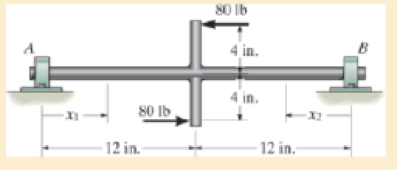
Chapter 12, Problem 12.134RP
Draw the bending-moment diagram for the shaft and then, from this diagram, sketch the deflection or elastic curve for the shaft’s centerline. Determine the equations of the elastic curve using the coordinates x1 and x2. Use the method of integration. EI is constant.
Expert Solution & Answer
Want to see the full answer?
Check out a sample textbook solution
Students have asked these similar questions
Find the torsion constant of the following beam cross section.
Draw the bending-moment diagram for the shaft and then, from this diagram, sketch the deflection or elastic curve for the shaft’s centerline. Determine the equations of the elastic curve using the coordinates x1 and x2. EI is constant
The simply supported beam is subjected to the force F = 700 N and the uniform distributed load with
intensity w = 150 N/m. Draw the shear force and bending moment diagrams (in your homework
documentation) and determine the equations for V(r) and M(x). Take a = 0 at point A.
19
F
a
Values for dimensions on the figure are given in the following table. Note the figure may not be to scale.
Variable Value
a
5.2 m
2.6 m
3.12 m
Support Reactions
The reaction at A is
N.
The reaction at D is
N.
Shear Force and Bending Moment Equations
In section AB:
V(x)=
N and M(x)=
N-m.
In section BC:
v(x)-
N and M(x)=
N-m.
In section CD:
V(x)-
N and M(x)=
N-m.
A
Chapter 12 Solutions
Mechanics of Materials
Ch. 12.2 - In each case, determine the internal bending...Ch. 12.2 - Determine the slope and deflection of end A of the...Ch. 12.2 - Determine the slope and deflection of end A of the...Ch. 12.2 - Determine the slope of end A of the cantilevered...Ch. 12.2 - Determine the maximum deflection of the simply...Ch. 12.2 - Determine the maximum deflection of the simply...Ch. 12.2 - Determine the slope of the simply supported beam...Ch. 12.2 - An L2 steel strap having a thickness of 0.125 in....Ch. 12.2 - The L2 steel blade of the band saw wraps around...Ch. 12.2 - A picture is taken of a man performing a pole...
Ch. 12.2 - Prob. 12.4PCh. 12.2 - 12-5. Determine the deflection of end C of the...Ch. 12.2 - Prob. 12.6PCh. 12.2 - Prob. 12.7PCh. 12.2 - Determine the equations of the elastic curve using...Ch. 12.2 - Determine the equations of the elastic curve for...Ch. 12.2 - 12-10. Determine the equations of the elastic...Ch. 12.2 - 12-11. Determine the deflection at the center of...Ch. 12.2 - Prob. 12.12PCh. 12.2 - Determine the maximum deflection of the beam and...Ch. 12.2 - The simply supported shaft has a moment of inertia...Ch. 12.2 - 12-15. The two wooden meter sticks are separated...Ch. 12.2 - Prob. 12.16PCh. 12.2 - Prob. 12.17PCh. 12.2 - The bar is supported by a roller constraint at B,...Ch. 12.2 - Determine the deflection at B of the bar in Prob....Ch. 12.2 - Determine the equations of the elastic curve using...Ch. 12.2 - Determine the maximum deflection of the solid...Ch. 12.2 - Determine the elastic curve for the cantilevered...Ch. 12.2 - Determine the equations of the elastic curve using...Ch. 12.2 - Determine the equations of the elastic curve using...Ch. 12.2 - The floor beam of the airplane is subjected to the...Ch. 12.2 - Determine the maximum deflection of the simply...Ch. 12.2 - Prob. 12.27PCh. 12.2 - Determine the slope at end B and the maximum...Ch. 12.2 - Determine the equation of the elastic curve using...Ch. 12.2 - Determine the equations of the elastic curve using...Ch. 12.3 - The shaft is supported at A by a journal bearing...Ch. 12.3 - The shaft supports the two pulley loads shown....Ch. 12.3 - 12-33. Determine the equation of the elastic...Ch. 12.3 - Determine the equation of the elastic curve, the...Ch. 12.3 - The beam is subjected to the load shown. Determine...Ch. 12.3 - Determine the equation of the elastic curve, the...Ch. 12.3 - Determine the equation of the elastic curve and...Ch. 12.3 - 12-38. The beam is subjected to the loads shown....Ch. 12.3 - Determine the maximum deflection of the...Ch. 12.3 - Determine the slope at A and the deflection of end...Ch. 12.3 - Determine the maximum deflection in region AB of...Ch. 12.3 - Prob. 12.42PCh. 12.3 - Prob. 12.43PCh. 12.3 - Prob. 12.44PCh. 12.3 - Prob. 12.45PCh. 12.3 - Prob. 12.46PCh. 12.3 - 12-47. The shaft is made of steel and has a...Ch. 12.3 - Prob. 12.48PCh. 12.3 - Determine the displacement at C and the slope at...Ch. 12.3 - Determine the equations of the slope and elastic...Ch. 12.4 - Determine the slope and deflection of end A of the...Ch. 12.4 - Determine the slope and deflection of end A of the...Ch. 12.4 - Determine the slope and deflection of end A of the...Ch. 12.4 - Determine the slope and deflection at A of the...Ch. 12.4 - Prob. 12.11FPCh. 12.4 - Determine the maximum deflection of the simply...Ch. 12.4 - Determine the slope and deflection at C. El is...Ch. 12.4 - Determine the slope and deflection at C. El is...Ch. 12.4 - Determine the deflection of end B of the...Ch. 12.4 - Prob. 12.54PCh. 12.4 - The composite simply supported steel shaft is...Ch. 12.4 - Prob. 12.56PCh. 12.4 - Prob. 12.57PCh. 12.4 - Determine the deflection at C and the slope of the...Ch. 12.4 - Prob. 12.59PCh. 12.4 - Prob. 12.60PCh. 12.4 - Determine the position a of the roller support B...Ch. 12.4 - Prob. 12.62PCh. 12.4 - Determine the slope and the deflection of end B of...Ch. 12.4 - Prob. 12.64PCh. 12.4 - Determine the slope at A and the displacement at...Ch. 12.4 - Determine the deflection at C and the slopes at...Ch. 12.4 - Determine the maximum deflection within region AB....Ch. 12.4 - Determine the slope at A and the maximum...Ch. 12.4 - Determine the slope at C and the deflection at B....Ch. 12.4 - Determine the slope at A and the maximum...Ch. 12.4 - Prob. 12.71PCh. 12.4 - Prob. 12.72PCh. 12.4 - Prob. 12.73PCh. 12.4 - The rod is constructed from two shafts for which...Ch. 12.4 - Prob. 12.75PCh. 12.4 - Determine the slope at point A and the maximum...Ch. 12.4 - Determine the position a of roller support B in...Ch. 12.4 - Determine the slope at B and deflection at C. El...Ch. 12.4 - Prob. 12.79PCh. 12.4 - Prob. 12.80PCh. 12.4 - Prob. 12.81PCh. 12.4 - Determine the maximum deflection of the beam. El...Ch. 12.5 - The W10 15 cantilevered beam is made of A-36...Ch. 12.5 - The W10 15 cantilevered beam is made of A-36...Ch. 12.5 - 12-85. Determine the slope and deflection at end C...Ch. 12.5 - 12-86. Determine the slope at A and the deflection...Ch. 12.5 - Prob. 12.87PCh. 12.5 - Prob. 12.88PCh. 12.5 - 12-89. The W8 × 24 simply supported beam is made...Ch. 12.5 - 12-90. The simply supported beam carries a uniform...Ch. 12.5 - Prob. 12.91PCh. 12.5 - *12-92. The W10 × 30 cantilevered beam is made of...Ch. 12.5 - The rod is pinned at its end A and attached to a...Ch. 12.5 - Prob. 12.94PCh. 12.5 - The pipe assembly consists of three equal-sized...Ch. 12.5 - *12-96. The framework consists of two A992 steel...Ch. 12.5 - Prob. 12.97PCh. 12.5 - 12-98. Determine the vertical deflection at the...Ch. 12.7 - Determine the reactions at the supports A and B,...Ch. 12.7 - Prob. 12.100PCh. 12.7 - Determine the reactions at the supports A, B, and...Ch. 12.7 - Determine the reactions at the supports A and B,...Ch. 12.7 - Determine the reactions at the supports A and B,...Ch. 12.7 - Prob. 12.104PCh. 12.7 - 12-105. Use discontinuity functions and determine...Ch. 12.7 - Determine the reactions at the support A and B. EI...Ch. 12.7 - 12-107. Determine the reactions at pin support A...Ch. 12.7 - Determine the moment reactions at the supports A...Ch. 12.7 - The beam has a constant E1I1 and is supported by...Ch. 12.7 - The beam is supported by a pin at A, a roller at...Ch. 12.8 - Determine the moment reactions at the supports A...Ch. 12.8 - Prob. 12.112PCh. 12.8 - Determine the vertical reaction at the journal...Ch. 12.8 - Determine the reactions at the supports A and B,...Ch. 12.8 - Prob. 12.115PCh. 12.8 - Determine the vertical reaction at the journal...Ch. 12.9 - Determine the reactions at the fixed support A and...Ch. 12.9 - Determine the reactions at the fixed support A and...Ch. 12.9 - Determine the reactions at the fixed support A and...Ch. 12.9 - Determine the reaction at the roller B. EI is...Ch. 12.9 - Determine the reaction at the roller B. EI is...Ch. 12.9 - Determine the reaction at the roller support B if...Ch. 12.9 - Determine the reactions at the journal bearing...Ch. 12.9 - Prob. 12.118PCh. 12.9 - 12-119. Determine the reactions at the supports A,...Ch. 12.9 - Prob. 12.120PCh. 12.9 - 12-121. Determine the deflection at the end B of...Ch. 12.9 - Determine the reactions at the supports A and B....Ch. 12.9 - Prob. 12.123PCh. 12.9 - Before the uniform distributed load is applied to...Ch. 12.9 - The fixed supported beam AB is strengthened using...Ch. 12.9 - 12-126. Determine the force in the spring. EI is...Ch. 12.9 - The beam is supported by the bolted supports at...Ch. 12.9 - Each of the two members is made from 6061-T6...Ch. 12.9 - The beam is made from a soft linear elastic...Ch. 12.9 - Prob. 12.130PCh. 12.9 - 12–131. The 1-in -diameter A-36 steel shaft is...Ch. 12.9 - Prob. 12.132PCh. 12 - Determine the equation of the elastic curve. Use...Ch. 12 - Draw the bending-moment diagram for the shaft and...Ch. 12 - Determine the moment reactions at the supports A...Ch. 12 - Specify the slope at A and the maximum deflection....Ch. 12 - Determine the maximum deflection between the...Ch. 12 - Determine the slope at B and the deflection at C....Ch. 12 - Determine the reactions, then draw the shear and...Ch. 12 - El is constant.Ch. 12 - Using the method of superposition, determine the...Ch. 12 - The rim on the flywheel has a thickness t, width...
Additional Engineering Textbook Solutions
Find more solutions based on key concepts
Find the change in length of side AB.
Mechanics of Materials, 7th Edition
List several uses of the arbor press.
Machine Tool Practices (10th Edition)
A number of common substances are
Some of these materials exhibit characteristics of both solid and fluid beha...
Fox and McDonald's Introduction to Fluid Mechanics
Three rigid bodies, 2,3, and 4, are connected by four springs as shown in the figure. A horizontal force of 1,0...
Introduction To Finite Element Analysis And Design
Consider a subsonic compressible flow in cartesian coordinates where the velocity potential is given by (x,y)=V...
Fundamentals of Aerodynamics
A 20-lb force is applied to the control rod AB as shown. Knowing that the length of the rod is 9 in. and that t...
Statics and Mechanics of Materials
Knowledge Booster


Learn more about
Need a deep-dive on the concept behind this application? Look no further. Learn more about this topic, mechanical-engineering and related others by exploring similar questions and additional content below.Similar questions
- 3 For the beam shown, find the reactions at the supports and plot the shear-force and bending-moment diagrams. V = 9 kN, V2 = 9 kN, V3 = 200 mm, and V4 = 1100 mm. ATAT-V3 Provide values at all key points shown in the given shear-force and bending-moment diagrams. X (mm) B A = B = C = D = E= F= P = Q = E * KN * KN * KN × KN KN x KN ✩ kN.mm *kN.mm D 0.00 Reaction force R₁ (left) = In the shear-force and bending-moment diagrams given, +V 0.00 X (mm) 6.3 kN and reaction force R2 (right) = P 11.7 kN. Q 0.00arrow_forwardDetermine the ff: •Internal bending moment at point c •internal shear force at point c •internal normal force at point c Asap please.arrow_forward2 - Use double integration to determine the elastic curve of the cantilever beam under lateral loading, where w is the load intensity (per unit length) at the left end. Flexural rigidity is El. Show that the tip displacement is: y w w14 U(L)=-30EIarrow_forward
- The beam is supported by a pin at point A and a roller at kN point B. A distributed load of W₁ = 8 - and an applied m force of F₁ = 12 kN are applied to the beam. The beam has an allowable bending stress of allow = 6 MPa. Neglect the weight and thickness of the beam. Take the origin for all functions to be at A., i.e. start at the left and go right. Must use positive sign convention for V and M. d3 1 d3 d1 W1 d1 B O h d2 F₁ Values for the figure are given in the following table. Note the figure may not be to scale. Dimensions for the whole beam Variable Value d₁ 4 m d₂ 2 marrow_forwardconsider the beam shown in. EI is constant. assume that EI is in kip * ft2. determine the expression for the elastic curve using the coordinate x1 for 0 < x1 < 20 ft, where x1 is in feet. v1 in ft answer in terms of the variables x1, E and I. determine the expression for the elastic curve using the coordinate x2 for 0 < x2 < 10 ft where x2 is in feet. v2 in ft. answer in terms of the variables x2, E and I. specify the deflection of the beam at C. vc in ft. answer in terms of E and I. specify the slope at A, measured counterclockwise from the positive x1 axis. Theta A in rad. answer in terms of E and I.arrow_forwardThe cantilevered beam has a rectangular cross-sectional area A, a moment of inertia I, and a modulus of elasticity E. If a load P acts at point B as shown, determine the displacement at B in the direction of P, accounting for bending, axial force, and shear.arrow_forward
- Part B - Moments of inertia of the cross section with respect to the y- and z-axesTo calculate the absolute maximum bending stress in the member using the flexure formula for unsymmetrical bending, the moments of inertia of the cross section must be calculated. Select the correct formulas for these values. Iy=? Part C - Neutral-axis angle due to externally applied momentsThe neutral-axis angle of the cross section being analyzed is the axis along which there is a zero stress value. Determine the neutral-axis angle, α, due to the externally applied moments as measured counterclockwise from the positive z axis in the yz plane.Express your answer to three significant figures and include the appropriate units. α=? Part D - Absolute maximum stress in cross section ABCDDetermine the absolute maximum stress, |σmax|, in cross section ABCD due to the two externally applied moments. |σmax|=?arrow_forwardDetermine the rotation (slope) and displacement at point B of the frame. Bending stiffness (EI) is constantarrow_forwardUse n=14. Determine the external reactions at the roller and pin supporting the above beam. Determine the internal reactions (shear and bending moment) at points B, D and F using the method of sections. Determine the shear and moment equations for the beam section under the triangular load, and the shear and moment equations for the beam section under the rectangular load. Draw the shear and bending moment diagrams using the area method showing the differential relations that exist between the load, shear and moment at each section of the beam. Label the diagrams properly indicating where the shear and moment values are positive and negative. Also show on the diagram all the maximum and minimum shear and moment values. arrow_forward
- Determine the maximum allowable intensity w of the uniform distributed load that can be applied to the beam. Assume w passes through the centroid of the beam’s cross-sectional area, and the beam is simply supported at A and B. The allowable bending stress is sallow = 165 MPa.arrow_forwardDetermine the bending strain energy in the simply supported beam. EI is constant.arrow_forwardA leaf spring 75 cm long is required to carry a central load of 8 kN. If the central deflection is not to exceed 2 cm and bending stress no greater than 200 MPa, determine the thickness, width and number of plates. Also compute the radius to which plates should be curved. As- sume width of plate to be 12 times its thickness and E = 200 GPa.arrow_forward
arrow_back_ios
SEE MORE QUESTIONS
arrow_forward_ios
Recommended textbooks for you
 Elements Of ElectromagneticsMechanical EngineeringISBN:9780190698614Author:Sadiku, Matthew N. O.Publisher:Oxford University Press
 Mechanics of Materials (10th Edition)Mechanical EngineeringISBN:9780134319650Author:Russell C. HibbelerPublisher:PEARSON
 Thermodynamics: An Engineering ApproachMechanical EngineeringISBN:9781259822674Author:Yunus A. Cengel Dr., Michael A. BolesPublisher:McGraw-Hill Education
 Control Systems EngineeringMechanical EngineeringISBN:9781118170519Author:Norman S. NisePublisher:WILEY
 Mechanics of Materials (MindTap Course List)Mechanical EngineeringISBN:9781337093347Author:Barry J. Goodno, James M. GerePublisher:Cengage Learning
 Engineering Mechanics: StaticsMechanical EngineeringISBN:9781118807330Author:James L. Meriam, L. G. Kraige, J. N. BoltonPublisher:WILEY
Elements Of Electromagnetics
Mechanical Engineering
ISBN:9780190698614
Author:Sadiku, Matthew N. O.
Publisher:Oxford University Press
Mechanics of Materials (10th Edition)
Mechanical Engineering
ISBN:9780134319650
Author:Russell C. Hibbeler
Publisher:PEARSON
Thermodynamics: An Engineering Approach
Mechanical Engineering
ISBN:9781259822674
Author:Yunus A. Cengel Dr., Michael A. Boles
Publisher:McGraw-Hill Education
Control Systems Engineering
Mechanical Engineering
ISBN:9781118170519
Author:Norman S. Nise
Publisher:WILEY
Mechanics of Materials (MindTap Course List)
Mechanical Engineering
ISBN:9781337093347
Author:Barry J. Goodno, James M. Gere
Publisher:Cengage Learning
Engineering Mechanics: Statics
Mechanical Engineering
ISBN:9781118807330
Author:James L. Meriam, L. G. Kraige, J. N. Bolton
Publisher:WILEY
Understanding Shear Force and Bending Moment Diagrams; Author: The Efficient Engineer;https://www.youtube.com/watch?v=C-FEVzI8oe8;License: Standard YouTube License, CC-BY
Bending Stress; Author: moodlemech;https://www.youtube.com/watch?v=9QIqewkE6xM;License: Standard Youtube License