
Statics and Mechanics of Materials (5th Edition)
5th Edition
ISBN: 9780134382593
Author: Russell C. Hibbeler
Publisher: PEARSON
expand_more
expand_more
format_list_bulleted
Concept explainers
Videos
Textbook Question
Chapter 10.3, Problem 6P
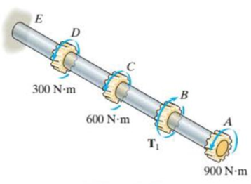
The solid aluminum shaft has a diameter of 50 mm and an allowable shear stress of τallow = 60 MPa. Determine the largest torque T1 that can be applied to the shaft if it is also subjected to the other torsional loadings. It is required that T1 act in the direction shown. Also, determine the maximum shear stress within regions CD and DE.
Probs. 10-6/7
Expert Solution & Answer
Want to see the full answer?
Check out a sample textbook solution
Students have asked these similar questions
=
5-6. The solid shaft has a diameter of 0.75 in. If it is subjected
to the torques shown, determine the maximum shear stress
developed in regions BC and DE of the shaft. The bearings at
A and Fallow free rotation of the shaft.
B
20 lb-ft
35 lb-ft
40 lb-ft
25 lb-ft
Probs. 5-6/7
The shaft consists of three concentric tubes, each
made from the same material and having the inner
and outer radii as shown. If the torque of T=800 N•m
is applied to the rigid disk fixed to its end, determine
the maximum shear stress in the shaft.
S •5-9. The shaft consists of three concentric tubes, each
made from the same material and having the inner and
outer radii shown. If a torque of T
the rigid disk fixed to its end, determine the maximum shear
stress in the shaft.
= 800 N• m is applied to
T= 800 N.m
r = 20 mm
ro = 25 mm
2 m
r; = 26 mm
ro = 30 mm
%3D
r; = 32 mm
38 mm
Prob. 5-9
The shaft has an outer diameter of 100 mm and an inner diameter of 80 mm. If it is subjected to
the three torques, plot the shear stress distribution along a radial line for the cross section
within region CD of the shaft. The smooth bearings at A and B do not resist torque.
E
10 kN m
B
15 kN m
5 kN-m
Chapter 10 Solutions
Statics and Mechanics of Materials (5th Edition)
Ch. 10.3 - Determine the internal torque at each section and...Ch. 10.3 - Determine the internal torque at each section and...Ch. 10.3 - Prob. 3PPCh. 10.3 - Prob. 4PPCh. 10.3 - Prob. 1FPCh. 10.3 - The hollow circular shaft is subjected to an...Ch. 10.3 - Prob. 3FPCh. 10.3 - Prob. 4FPCh. 10.3 - Determine the maximum shear stress in the shaft at...Ch. 10.3 - Prob. 6FP
Ch. 10.3 - The solid 50-mm-diameter shaft is subjected to the...Ch. 10.3 - Prob. 8FPCh. 10.3 - Prob. 1PCh. 10.3 - Prob. 2PCh. 10.3 - A shaft is made of an aluminum alloy having an...Ch. 10.3 - The copper pipe has an outer diameter of 40 mm and...Ch. 10.3 - The copper pipe has an outer diameter of 2.50 in....Ch. 10.3 - The solid aluminum shaft has a diameter of 50 mm...Ch. 10.3 - The solid aluminum shaft has a diameter of 50 mm....Ch. 10.3 - The solid 30-mm-diameter shaft is used to transmit...Ch. 10.3 - The solid shaft is fixed to the support at C and...Ch. 10.3 - The link acts as part of the elevator control for...Ch. 10.3 - The assembly consists of two sections of...Ch. 10.3 - The shaft has an outer diameter of 100 mm and an...Ch. 10.3 - Prob. 13PCh. 10.3 - Prob. 14PCh. 10.3 - Prob. 15PCh. 10.3 - Prob. 16PCh. 10.3 - The rod has a diameter of 1 in. and a weight of 10...Ch. 10.3 - Prob. 18PCh. 10.3 - Prob. 19PCh. 10.3 - Prob. 20PCh. 10.3 - Prob. 21PCh. 10.3 - The 60-mm-diametcr solid shaft is subjected to the...Ch. 10.3 - Prob. 23PCh. 10.3 - The 60-mm-diameter solid shaft is subjected to the...Ch. 10.3 - Prob. 25PCh. 10.3 - The pump operates using the motor that has a power...Ch. 10.3 - Prob. 27PCh. 10.3 - Prob. 28PCh. 10.3 - Prob. 29PCh. 10.3 - The gear motor can develop 2 hp when it turns at...Ch. 10.3 - Prob. 31PCh. 10.3 - The 6-hp reducer motor can turn at 1200 rev/min....Ch. 10.3 - Prob. 33PCh. 10.3 - Prob. 34PCh. 10.4 - The 60-mm-diameter steel shaft is subjected to the...Ch. 10.4 - Prob. 10FPCh. 10.4 - The hollow 6061-T6 aluminum shaft has an outer and...Ch. 10.4 - A series of gears are mounted on the...Ch. 10.4 - Prob. 13FPCh. 10.4 - The 80-mm-diameter shaft is made of steel. If it...Ch. 10.4 - The propellers of a ship are connected to an A-36...Ch. 10.4 - Prob. 36PCh. 10.4 - The splined ends and gears attached to the A992...Ch. 10.4 - Prob. 38PCh. 10.4 - The 60-mm-diameter shaft is made of 6061-T6...Ch. 10.4 - The 60-mm-diameter shaft is made of 6061-T6...Ch. 10.4 - Prob. 41PCh. 10.4 - Prob. 42PCh. 10.4 - Gear B supplies 15 kW of power, while gears A, C,...Ch. 10.4 - Prob. 44PCh. 10.4 - The turbine develops 150 kW of power, which is...Ch. 10.4 - Prob. 46PCh. 10.4 - Prob. 47PCh. 10.4 - Prob. 48PCh. 10.4 - The A 992 steel shaft has a diameter of 50 mm and...Ch. 10.4 - The turbine develops 300 kW of power, which is...Ch. 10.4 - Prob. 51PCh. 10.4 - The device shown is used to mix soils in order to...Ch. 10.4 - The 6-in.-diameter L-2 steel shaft on the turbine...Ch. 10.4 - The A-36 hollow steel shaft is 2 m long and has an...Ch. 10.4 - The A-36 solid steel shaft is 3 m long and has a...Ch. 10.4 - Prob. 56PCh. 10.4 - Prob. 57PCh. 10.4 - Prob. 58PCh. 10.4 - The tubular drive shaft for the propeller of a...Ch. 10.4 - The 60-mm diameter solid shaft is made of 2014-T6...Ch. 10.4 - Prob. 61PCh. 10.5 - The steel shaft has a diameter of 40 mm and is...Ch. 10.5 - The A992 steel shaft has a diameter of 60 mm and...Ch. 10.5 - The steel shaft is made from two segments: AC has...Ch. 10.5 - The bronze C86100 pipe has an outer diameter of...Ch. 10.5 - The bronze C86100 pipe has an outer diameter of...Ch. 10.5 - Prob. 67PCh. 10.5 - Prob. 68PCh. 10.5 - The Am1004-T61 magnesium tube is bonded to the...Ch. 10.5 - The Am1004-T61 magnesium tube is bonded to the...Ch. 10.5 - The two shafts are made of A-36 steel. Each has a...Ch. 10.5 - Prob. 72PCh. 10.5 - Prob. 73PCh. 10.5 - Prob. 74PCh. 10.5 - Prob. 75PCh. 10.5 - The composite shaft consists of a mid-section that...Ch. 10.5 - Prob. 77PCh. 10.5 - The tapered shaft is confined by the fixed...Ch. 10.5 - Prob. 79PCh. 10 - The shaft is made of A992 steel and has an...Ch. 10 - The shaft is made of A992 steel and has an...Ch. 10 - The A-36 steel circular tube is subjected to a...Ch. 10 - Prob. 4RPCh. 10 - Prob. 5RPCh. 10 - Prob. 6RPCh. 10 - Prob. 7RPCh. 10 - Prob. 8RPCh. 10 - The 60-mm-diameter shaft rotates at 300 rev/min....
Knowledge Booster


Learn more about
Need a deep-dive on the concept behind this application? Look no further. Learn more about this topic, mechanical-engineering and related others by exploring similar questions and additional content below.Similar questions
- The shaft is made from a solid steel section AB and a tubular portion made of steel and having a brass core. If it is fixed to a rigid support at A, and a torque of T = 50 lb.ft is applied to it at C, determine the rotation angle that occurs at C relative to A and compute the maximum shear stress and maximum shear strain in the brass and steel. Take Gst = 11500 ksi, Gbr = 5600 Ksi. 3 ft 0.5 in. B 1 in. T = 50 lb•ftarrow_forward10-21. The shaft has an outer diameter of 100 mm and an inner diameter of 80 mm. If it is subjected to the three torques, plot the shear stress distributicn along a radial line for the cross section within region CD of the shaft. The smooth bearings at A and B do not resist tarque. 10 kN-m 15 kN m 5 kN-marrow_forwardThe shaft has an outer diameter of 1.5 in. and an inner diameter of 0.8 in. If it is subjected to the applied torques as shown, determine the shear stress distribution on the cross-section within region EA. The smooth bearings at A and B do not resist torque 1500 lb-in. E 2100 lb-in. B 600 lb.in.arrow_forward
- The solid steel shaft AC has a diameter of 25 mm and is supported by smooth bearings at D and E. It is coupled to a motor at C, which delivers 3 kW of power to the shaft while it is turning at 50 rev>s. If gears A and B remove1 kW and 2 kW, respectively, determine the maximum shear stress in the shaft within regions AB and BC. The shaft is free to turn in its support bearings D and E.arrow_forwardThe solid circular shaft is subjected to an internal torque of T = 5 kN # m. Determine the shear stress at points A and B. Represent each state of stress on a volume element.arrow_forwardIf the solid shaft is made from red brass C83400 and it is subjected to a torque T = 6 kip # ft at B, determine the maximum shear stress developed in segments AB and BC.arrow_forward
- 10-3. A shaft is made of an aluminum alloy having an alkowable shear stress of T - 100 MPa. If the diameter of the shaft is 100 mm, determine the maximum torque T that can be transmitted. What would be the maximum torque T'if a 75-mm-diameter hole were bared through the shaft? Sketch the shear-stress distribution along a radial line in each case.arrow_forwardThe steel step shaft has allowable shear stress of tallow = 8 MPa. If the transition between the cross-sections has a radius r = 4 mm, determine the maximum torque T that can be applied.arrow_forward*10-8. The solid shaft is fixed to the support at Cand subjected to the torsional loadings shown. Determine the shear stress at points A and B and sketch the shear stress on valume elements located at these points. 10 kN-m 75 mm 4 kN m So mm T5 mmarrow_forward
- The solid steel shaft DF has a diameter of 25 mm and is supported by smooth bearings at D and E. It is coupled to a motor at F, which delivers 12 kW of power to the shaft while it is turning at 50 rev>s. If gears A, B, and C remove3 kW, 4 kW, and 5 kW respectively, determine the maximum shear stress in the shaft within regions CF and BC. The shaft is free to turn in its support bearings D and E.arrow_forward*10-20. The shaft has an cuter diameter of 100 mm and an inner diameter of 80 mm. If it is subjected to the three torques, determine the absolute maximum shear stress in the shaft. The smooth bearings A and B do not resist torque. 10 kN-m 15 kN m 5 kN-marrow_forward10-65. The shaft is made of 12 tool steel, has a diameter of 40 mm, and is fixed at its ends A and B. If it is subjected to the torque, determime the maximum shear stress in regions AC and CB. 2 kN-m 600 mm B00 mimarrow_forward
arrow_back_ios
SEE MORE QUESTIONS
arrow_forward_ios
Recommended textbooks for you
 Elements Of ElectromagneticsMechanical EngineeringISBN:9780190698614Author:Sadiku, Matthew N. O.Publisher:Oxford University Press
 Mechanics of Materials (10th Edition)Mechanical EngineeringISBN:9780134319650Author:Russell C. HibbelerPublisher:PEARSON
 Thermodynamics: An Engineering ApproachMechanical EngineeringISBN:9781259822674Author:Yunus A. Cengel Dr., Michael A. BolesPublisher:McGraw-Hill Education
 Control Systems EngineeringMechanical EngineeringISBN:9781118170519Author:Norman S. NisePublisher:WILEY
 Mechanics of Materials (MindTap Course List)Mechanical EngineeringISBN:9781337093347Author:Barry J. Goodno, James M. GerePublisher:Cengage Learning
 Engineering Mechanics: StaticsMechanical EngineeringISBN:9781118807330Author:James L. Meriam, L. G. Kraige, J. N. BoltonPublisher:WILEY
Elements Of Electromagnetics
Mechanical Engineering
ISBN:9780190698614
Author:Sadiku, Matthew N. O.
Publisher:Oxford University Press
Mechanics of Materials (10th Edition)
Mechanical Engineering
ISBN:9780134319650
Author:Russell C. Hibbeler
Publisher:PEARSON
Thermodynamics: An Engineering Approach
Mechanical Engineering
ISBN:9781259822674
Author:Yunus A. Cengel Dr., Michael A. Boles
Publisher:McGraw-Hill Education
Control Systems Engineering
Mechanical Engineering
ISBN:9781118170519
Author:Norman S. Nise
Publisher:WILEY
Mechanics of Materials (MindTap Course List)
Mechanical Engineering
ISBN:9781337093347
Author:Barry J. Goodno, James M. Gere
Publisher:Cengage Learning
Engineering Mechanics: Statics
Mechanical Engineering
ISBN:9781118807330
Author:James L. Meriam, L. G. Kraige, J. N. Bolton
Publisher:WILEY
Everything About COMBINED LOADING in 10 Minutes! Mechanics of Materials; Author: Less Boring Lectures;https://www.youtube.com/watch?v=N-PlI900hSg;License: Standard youtube license