
Statics and Mechanics of Materials (5th Edition)
5th Edition
ISBN: 9780134382593
Author: Russell C. Hibbeler
Publisher: PEARSON
expand_more
expand_more
format_list_bulleted
Concept explainers
Videos
Textbook Question
Chapter 10.3, Problem 10P
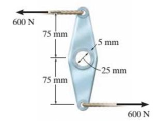
The link acts as part of the elevator control for a small airplane. If the attached aluminum tube has an inner diameter of 25 mm and a wall thickness of 5 mm. determine the maximum shear stress in the tube when the cable force of 600 N is applied to the cables. Also, sketch the shear-stress distribution over the cross section.
Prob. 10-10
Expert Solution & Answer
Want to see the full answer?
Check out a sample textbook solution
Students have asked these similar questions
The long bolt passes through the 20-mm-thick plate. If the force in
the bolt shank is 9 kN, determine the average normal stress in the
shank, the average shear stress along the cylindrical area of the
plate defined by the section lines a-a, and the average shear stress
in the bolt head along the cylindrical area defined by the section
lines b-b.
18 mm
b
8 mm
7 mm
20 mm
9 kN
7-35. The two members used in the construction of an
aircraft fuselage are joined together using a 30° fish-mouth
weld. Determine the average normal and average shear
stress on the plane of each weld. Assume each inclined
plane supports a horizontal force of 2 kN.
375 mm 30
4 kN
4 kN
25 mm
30
The long bolt passes through the 30-mm-thick
plate. If the force in the bolt shank is 8 kN, determine the
average normal stress in the shank, the average shear stress
along the cylindrical area of the plate defined by the section
lines a-a, and the average shear stress in the bolt head along
the cylindrical area defined by the section lines b-b.
8 mm
7 mm
18 mm
30 mm
Chapter 10 Solutions
Statics and Mechanics of Materials (5th Edition)
Ch. 10.3 - Determine the internal torque at each section and...Ch. 10.3 - Determine the internal torque at each section and...Ch. 10.3 - Prob. 3PPCh. 10.3 - Prob. 4PPCh. 10.3 - Prob. 1FPCh. 10.3 - The hollow circular shaft is subjected to an...Ch. 10.3 - Prob. 3FPCh. 10.3 - Prob. 4FPCh. 10.3 - Determine the maximum shear stress in the shaft at...Ch. 10.3 - Prob. 6FP
Ch. 10.3 - The solid 50-mm-diameter shaft is subjected to the...Ch. 10.3 - Prob. 8FPCh. 10.3 - Prob. 1PCh. 10.3 - Prob. 2PCh. 10.3 - A shaft is made of an aluminum alloy having an...Ch. 10.3 - The copper pipe has an outer diameter of 40 mm and...Ch. 10.3 - The copper pipe has an outer diameter of 2.50 in....Ch. 10.3 - The solid aluminum shaft has a diameter of 50 mm...Ch. 10.3 - The solid aluminum shaft has a diameter of 50 mm....Ch. 10.3 - The solid 30-mm-diameter shaft is used to transmit...Ch. 10.3 - The solid shaft is fixed to the support at C and...Ch. 10.3 - The link acts as part of the elevator control for...Ch. 10.3 - The assembly consists of two sections of...Ch. 10.3 - The shaft has an outer diameter of 100 mm and an...Ch. 10.3 - Prob. 13PCh. 10.3 - Prob. 14PCh. 10.3 - Prob. 15PCh. 10.3 - Prob. 16PCh. 10.3 - The rod has a diameter of 1 in. and a weight of 10...Ch. 10.3 - Prob. 18PCh. 10.3 - Prob. 19PCh. 10.3 - Prob. 20PCh. 10.3 - Prob. 21PCh. 10.3 - The 60-mm-diametcr solid shaft is subjected to the...Ch. 10.3 - Prob. 23PCh. 10.3 - The 60-mm-diameter solid shaft is subjected to the...Ch. 10.3 - Prob. 25PCh. 10.3 - The pump operates using the motor that has a power...Ch. 10.3 - Prob. 27PCh. 10.3 - Prob. 28PCh. 10.3 - Prob. 29PCh. 10.3 - The gear motor can develop 2 hp when it turns at...Ch. 10.3 - Prob. 31PCh. 10.3 - The 6-hp reducer motor can turn at 1200 rev/min....Ch. 10.3 - Prob. 33PCh. 10.3 - Prob. 34PCh. 10.4 - The 60-mm-diameter steel shaft is subjected to the...Ch. 10.4 - Prob. 10FPCh. 10.4 - The hollow 6061-T6 aluminum shaft has an outer and...Ch. 10.4 - A series of gears are mounted on the...Ch. 10.4 - Prob. 13FPCh. 10.4 - The 80-mm-diameter shaft is made of steel. If it...Ch. 10.4 - The propellers of a ship are connected to an A-36...Ch. 10.4 - Prob. 36PCh. 10.4 - The splined ends and gears attached to the A992...Ch. 10.4 - Prob. 38PCh. 10.4 - The 60-mm-diameter shaft is made of 6061-T6...Ch. 10.4 - The 60-mm-diameter shaft is made of 6061-T6...Ch. 10.4 - Prob. 41PCh. 10.4 - Prob. 42PCh. 10.4 - Gear B supplies 15 kW of power, while gears A, C,...Ch. 10.4 - Prob. 44PCh. 10.4 - The turbine develops 150 kW of power, which is...Ch. 10.4 - Prob. 46PCh. 10.4 - Prob. 47PCh. 10.4 - Prob. 48PCh. 10.4 - The A 992 steel shaft has a diameter of 50 mm and...Ch. 10.4 - The turbine develops 300 kW of power, which is...Ch. 10.4 - Prob. 51PCh. 10.4 - The device shown is used to mix soils in order to...Ch. 10.4 - The 6-in.-diameter L-2 steel shaft on the turbine...Ch. 10.4 - The A-36 hollow steel shaft is 2 m long and has an...Ch. 10.4 - The A-36 solid steel shaft is 3 m long and has a...Ch. 10.4 - Prob. 56PCh. 10.4 - Prob. 57PCh. 10.4 - Prob. 58PCh. 10.4 - The tubular drive shaft for the propeller of a...Ch. 10.4 - The 60-mm diameter solid shaft is made of 2014-T6...Ch. 10.4 - Prob. 61PCh. 10.5 - The steel shaft has a diameter of 40 mm and is...Ch. 10.5 - The A992 steel shaft has a diameter of 60 mm and...Ch. 10.5 - The steel shaft is made from two segments: AC has...Ch. 10.5 - The bronze C86100 pipe has an outer diameter of...Ch. 10.5 - The bronze C86100 pipe has an outer diameter of...Ch. 10.5 - Prob. 67PCh. 10.5 - Prob. 68PCh. 10.5 - The Am1004-T61 magnesium tube is bonded to the...Ch. 10.5 - The Am1004-T61 magnesium tube is bonded to the...Ch. 10.5 - The two shafts are made of A-36 steel. Each has a...Ch. 10.5 - Prob. 72PCh. 10.5 - Prob. 73PCh. 10.5 - Prob. 74PCh. 10.5 - Prob. 75PCh. 10.5 - The composite shaft consists of a mid-section that...Ch. 10.5 - Prob. 77PCh. 10.5 - The tapered shaft is confined by the fixed...Ch. 10.5 - Prob. 79PCh. 10 - The shaft is made of A992 steel and has an...Ch. 10 - The shaft is made of A992 steel and has an...Ch. 10 - The A-36 steel circular tube is subjected to a...Ch. 10 - Prob. 4RPCh. 10 - Prob. 5RPCh. 10 - Prob. 6RPCh. 10 - Prob. 7RPCh. 10 - Prob. 8RPCh. 10 - The 60-mm-diameter shaft rotates at 300 rev/min....
Knowledge Booster


Learn more about
Need a deep-dive on the concept behind this application? Look no further. Learn more about this topic, mechanical-engineering and related others by exploring similar questions and additional content below.Similar questions
- 8. If the allowable shear stress for each of the 10-mm-diameter steel pins at A, B, and C is Ellow = 90 MPa, and the allowable normal stress for the 13-mm-diameter rod is Glow = 150 MPa, determine the largest intensity w of the uniform distributed load that can be suspended from the beam. 1.2 m B 0.9 g Probs. 1-87/88arrow_forwardThe shaft is supported by a thrust bearing at A and a journal bearing at B. If P = 20 kN, determine the absolute maximum shear stress in the shaft.arrow_forwardThe 10-mm-diameter steel bolt is surrounded by a bronze sleeve. The outer diameter of this sleeve is 20 mm, and its inner diameter is 10 mm. If the bolt is subjected to a compressive force of P = 20 kN, determine the average normal stress in the steel and the bronze. Est = 200 GPa, Ebr = 100 GPa.arrow_forward
- The shaft is hollow from A to B and solid from B to C. Determine the maximum shear stress in the shaft. The shaft has an outer diameter of 80 mm, and the thickness of the wall of the hollow segment is 10 mm.arrow_forwardThe solid shaft is fixed to the support at C and subjected to the torsional loadings. Determine the shear stress at points A and B on the surface, and sketch the shear stress on volume elements located at these points.arrow_forward*10-8. The solid shaft is fixed to the support at Cand subjected to the torsional loadings shown. Determine the shear stress at points A and B and sketch the shear stress on valume elements located at these points. 10 kN-m 75 mm 4 kN m So mm T5 mmarrow_forward
- The assembly consists of two sections of galvanized steel pipe connected together using a reducing coupling at B. The smaller pipe has an outer diameter of 0.75 in. and an inner diameter of 0.68 in., whereas the larger pipe has an outer diameter of 1 in. and an inner diameter of 0.86 in. If the pipe istightly secured to the wall at C, determine the maximum shear stress in each section of the pipe when the couple is applied to the handles of the wrench.arrow_forward7-54. The lever is attached to the shaft A using a key that has a width d and length of 25 mm. If the shaft is fixed and a vertical force of 200 N is applied perpendicular to the handle, determine the dimension d if the allowable shear stress for the key is Talloe - 35 MPa. -20 mm 500 mm 200 Narrow_forwardThe long bolt passes through the 30-mm-thick plate. If the force in the bolt shank is 8 kN, determine the average normal stress in the shank, the average shear stress along the cylindrical area of the plate defined by the section linesa–a, and the average shear stress in the bolt head along the cylindrical area defined by the section lines b–b.arrow_forward
- 9-39. Determine the principal stresses acting at point B, which is located just on the web, below the horizontal segment on the cross section. Show the results on a properly oriented element located at this point. Although it is not very accurate, use the shear formula to calculate the shear stress. 12 mm A 150 mm 130 mm- B A -800 mm- 300 mm B -15 mm 6 kN Prob. 9-39 5arrow_forward7-42. If P- 15 kN, determine the average shear stress in the pins at A, B, and C. All pins are in double shear, and each has a diameter of 18 mm. 4P 4P 2P 0.5 m 0.5m -15m 1.5 30arrow_forward9-63. When the temperature is at 30 °C, the A-36 steel pipe fits snugly between the two fuel tanks When fuel flows through the pipe, the temperatures at ends A and B rise to 130 °C and 80 °C, respectively. If the temperature drop along the pipe is linear, determine the average normal stress developed in the pipe. Assume each tank provides a rigid support at A and B. 150 mm. 10 mm- Section a -aarrow_forward
arrow_back_ios
SEE MORE QUESTIONS
arrow_forward_ios
Recommended textbooks for you
 Elements Of ElectromagneticsMechanical EngineeringISBN:9780190698614Author:Sadiku, Matthew N. O.Publisher:Oxford University Press
 Mechanics of Materials (10th Edition)Mechanical EngineeringISBN:9780134319650Author:Russell C. HibbelerPublisher:PEARSON
 Thermodynamics: An Engineering ApproachMechanical EngineeringISBN:9781259822674Author:Yunus A. Cengel Dr., Michael A. BolesPublisher:McGraw-Hill Education
 Control Systems EngineeringMechanical EngineeringISBN:9781118170519Author:Norman S. NisePublisher:WILEY
 Mechanics of Materials (MindTap Course List)Mechanical EngineeringISBN:9781337093347Author:Barry J. Goodno, James M. GerePublisher:Cengage Learning
 Engineering Mechanics: StaticsMechanical EngineeringISBN:9781118807330Author:James L. Meriam, L. G. Kraige, J. N. BoltonPublisher:WILEY
Elements Of Electromagnetics
Mechanical Engineering
ISBN:9780190698614
Author:Sadiku, Matthew N. O.
Publisher:Oxford University Press
Mechanics of Materials (10th Edition)
Mechanical Engineering
ISBN:9780134319650
Author:Russell C. Hibbeler
Publisher:PEARSON
Thermodynamics: An Engineering Approach
Mechanical Engineering
ISBN:9781259822674
Author:Yunus A. Cengel Dr., Michael A. Boles
Publisher:McGraw-Hill Education
Control Systems Engineering
Mechanical Engineering
ISBN:9781118170519
Author:Norman S. Nise
Publisher:WILEY
Mechanics of Materials (MindTap Course List)
Mechanical Engineering
ISBN:9781337093347
Author:Barry J. Goodno, James M. Gere
Publisher:Cengage Learning
Engineering Mechanics: Statics
Mechanical Engineering
ISBN:9781118807330
Author:James L. Meriam, L. G. Kraige, J. N. Bolton
Publisher:WILEY
Pressure Vessels Introduction; Author: Engineering and Design Solutions;https://www.youtube.com/watch?v=Z1J97IpFc2k;License: Standard youtube license