
Statics and Mechanics of Materials (5th Edition)
5th Edition
ISBN: 9780134382593
Author: Russell C. Hibbeler
Publisher: PEARSON
expand_more
expand_more
format_list_bulleted
Concept explainers
Videos
Textbook Question
Chapter 10, Problem 3RP
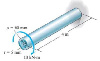
The A-36 steel circular tube is subjected to a torque of 10 kN · m. Determine the shear stress at the mean radius ρ = 60 mm and calculate the angle of twist of the tube if it is 4 m long and fixed at its far end. Solve the problem using Eqs. 10-7 and 10-15 and using Eqs. 10-18 and 10-20.
Prob. R10-3
Expert Solution & Answer
Want to see the full answer?
Check out a sample textbook solution
Students have asked these similar questions
The steel shaft is formed by attaching a hollow shaft to a solid shaft. Determine the shear stress (in Pa) in the hollow shaft
using the maximum torque T that can be applied to the ends of the shaft without exceeding a shear stress of 70066350 Pa and
angle of twist of 2.5° for the whole shaft. Use 6 = 83000000000 Pafor the shaft, x = 2.25 m, and y = 1.63 m. Round off the final
answer to two decimal places.
T
100 mm
70 mm
70 mm
y
The 304 stainless steel tube has a thickness of 10 mm. If the allowable shear stress is tallow = 80 MPa, determine the maximum torque T that it can transmit. Also, what is the angle of twist of one end of the tube with respect to the other if the tube is 4 m long? The mean dimensions are shown.
The steel shaft is formed by attaching a hollow shaft to a solid shaft. Determine the shear stress (in Pa) in the hollow shaft using the maximum torque T that can be applied to the ends of the shaft without exceeding a shear stress of 70191543 Pa and angle of twist of 2.6ᴼ for the whole shaft. Use G = 83000000000 Pafor the shaft, x = 2.23 m, and y = 1.76 m. Round off the final answer to two decimal places.
Chapter 10 Solutions
Statics and Mechanics of Materials (5th Edition)
Ch. 10.3 - Determine the internal torque at each section and...Ch. 10.3 - Determine the internal torque at each section and...Ch. 10.3 - Prob. 3PPCh. 10.3 - Prob. 4PPCh. 10.3 - Prob. 1FPCh. 10.3 - The hollow circular shaft is subjected to an...Ch. 10.3 - Prob. 3FPCh. 10.3 - Prob. 4FPCh. 10.3 - Determine the maximum shear stress in the shaft at...Ch. 10.3 - Prob. 6FP
Ch. 10.3 - The solid 50-mm-diameter shaft is subjected to the...Ch. 10.3 - Prob. 8FPCh. 10.3 - Prob. 1PCh. 10.3 - Prob. 2PCh. 10.3 - A shaft is made of an aluminum alloy having an...Ch. 10.3 - The copper pipe has an outer diameter of 40 mm and...Ch. 10.3 - The copper pipe has an outer diameter of 2.50 in....Ch. 10.3 - The solid aluminum shaft has a diameter of 50 mm...Ch. 10.3 - The solid aluminum shaft has a diameter of 50 mm....Ch. 10.3 - The solid 30-mm-diameter shaft is used to transmit...Ch. 10.3 - The solid shaft is fixed to the support at C and...Ch. 10.3 - The link acts as part of the elevator control for...Ch. 10.3 - The assembly consists of two sections of...Ch. 10.3 - The shaft has an outer diameter of 100 mm and an...Ch. 10.3 - Prob. 13PCh. 10.3 - Prob. 14PCh. 10.3 - Prob. 15PCh. 10.3 - Prob. 16PCh. 10.3 - The rod has a diameter of 1 in. and a weight of 10...Ch. 10.3 - Prob. 18PCh. 10.3 - Prob. 19PCh. 10.3 - Prob. 20PCh. 10.3 - Prob. 21PCh. 10.3 - The 60-mm-diametcr solid shaft is subjected to the...Ch. 10.3 - Prob. 23PCh. 10.3 - The 60-mm-diameter solid shaft is subjected to the...Ch. 10.3 - Prob. 25PCh. 10.3 - The pump operates using the motor that has a power...Ch. 10.3 - Prob. 27PCh. 10.3 - Prob. 28PCh. 10.3 - Prob. 29PCh. 10.3 - The gear motor can develop 2 hp when it turns at...Ch. 10.3 - Prob. 31PCh. 10.3 - The 6-hp reducer motor can turn at 1200 rev/min....Ch. 10.3 - Prob. 33PCh. 10.3 - Prob. 34PCh. 10.4 - The 60-mm-diameter steel shaft is subjected to the...Ch. 10.4 - Prob. 10FPCh. 10.4 - The hollow 6061-T6 aluminum shaft has an outer and...Ch. 10.4 - A series of gears are mounted on the...Ch. 10.4 - Prob. 13FPCh. 10.4 - The 80-mm-diameter shaft is made of steel. If it...Ch. 10.4 - The propellers of a ship are connected to an A-36...Ch. 10.4 - Prob. 36PCh. 10.4 - The splined ends and gears attached to the A992...Ch. 10.4 - Prob. 38PCh. 10.4 - The 60-mm-diameter shaft is made of 6061-T6...Ch. 10.4 - The 60-mm-diameter shaft is made of 6061-T6...Ch. 10.4 - Prob. 41PCh. 10.4 - Prob. 42PCh. 10.4 - Gear B supplies 15 kW of power, while gears A, C,...Ch. 10.4 - Prob. 44PCh. 10.4 - The turbine develops 150 kW of power, which is...Ch. 10.4 - Prob. 46PCh. 10.4 - Prob. 47PCh. 10.4 - Prob. 48PCh. 10.4 - The A 992 steel shaft has a diameter of 50 mm and...Ch. 10.4 - The turbine develops 300 kW of power, which is...Ch. 10.4 - Prob. 51PCh. 10.4 - The device shown is used to mix soils in order to...Ch. 10.4 - The 6-in.-diameter L-2 steel shaft on the turbine...Ch. 10.4 - The A-36 hollow steel shaft is 2 m long and has an...Ch. 10.4 - The A-36 solid steel shaft is 3 m long and has a...Ch. 10.4 - Prob. 56PCh. 10.4 - Prob. 57PCh. 10.4 - Prob. 58PCh. 10.4 - The tubular drive shaft for the propeller of a...Ch. 10.4 - The 60-mm diameter solid shaft is made of 2014-T6...Ch. 10.4 - Prob. 61PCh. 10.5 - The steel shaft has a diameter of 40 mm and is...Ch. 10.5 - The A992 steel shaft has a diameter of 60 mm and...Ch. 10.5 - The steel shaft is made from two segments: AC has...Ch. 10.5 - The bronze C86100 pipe has an outer diameter of...Ch. 10.5 - The bronze C86100 pipe has an outer diameter of...Ch. 10.5 - Prob. 67PCh. 10.5 - Prob. 68PCh. 10.5 - The Am1004-T61 magnesium tube is bonded to the...Ch. 10.5 - The Am1004-T61 magnesium tube is bonded to the...Ch. 10.5 - The two shafts are made of A-36 steel. Each has a...Ch. 10.5 - Prob. 72PCh. 10.5 - Prob. 73PCh. 10.5 - Prob. 74PCh. 10.5 - Prob. 75PCh. 10.5 - The composite shaft consists of a mid-section that...Ch. 10.5 - Prob. 77PCh. 10.5 - The tapered shaft is confined by the fixed...Ch. 10.5 - Prob. 79PCh. 10 - The shaft is made of A992 steel and has an...Ch. 10 - The shaft is made of A992 steel and has an...Ch. 10 - The A-36 steel circular tube is subjected to a...Ch. 10 - Prob. 4RPCh. 10 - Prob. 5RPCh. 10 - Prob. 6RPCh. 10 - Prob. 7RPCh. 10 - Prob. 8RPCh. 10 - The 60-mm-diameter shaft rotates at 300 rev/min....
Knowledge Booster


Learn more about
Need a deep-dive on the concept behind this application? Look no further. Learn more about this topic, mechanical-engineering and related others by exploring similar questions and additional content below.Similar questions
- The steel shaft is formed by attaching a hollow shaft to a solid shaft. Determine the shear stress in the solid shaft (in Pa) using the maximum torque T that can be applied to the ends of the shaft without exceeding a shear stress of 70055451 Pa and angle of twist of 2.38ᴼ for the whole shaft. Use G = 83000000000 Pafor the shaft, x = 2.25 m, and y = 1.55 m. Round off the final answer to two decimal places.arrow_forwardThe steel shaft is formed by attaching a hollow shaft to a solid shaft. Determine the maximum torque T that can be applied to the ends of the shaft without exceeding a shear stress of 70 MPa or an angle of twist of 2.5 degrees in the 3.5-m length. Use G = 83 GPa for steel. 100 mm 70 mm 70 mm C 15m- 2 marrow_forwardThe shaft consists of three concentric tubes, each made from the same material and having inner and outer radii as given below. Length of shaft is 2m. One end is fixed to the wall and to the other end a disc is attached. If a torque of T =800 N.m is applied at the disc end, determine the maximum shear stress in the shaft. 1. Inner tube: r; = 20mm, r, = 25 mm 2. Center tube: r; = 26 mm, r. = 30 mm 3. Outer tube: r = 32mm, r, = 38mmarrow_forward
- The steel step shaft has an allowable shear stress of Fallow 9 MPa. If the transition between the cross-sections has a radius r-4 mm, determine the maximum torque T that can be applied. Take K-1.25. 20 mm 72 N.m T 50 mm 20 mm 7/2 The maximum torque T that can be applied is. Note: Please enter your answer with three significant digits after the decimal point. Take the torque as positive since the problem does not have multiple sections before the step.arrow_forwardThe steel shaft is formed by attaching a hollow shaft to a solid shaft. Determine the shear stress in the solid shaft (in Pa) using the maximum torque T that can be applied to the ends of the shaft without exceeding a shear stress of 70113826 Pa and angle of twist of 2.20 for the whole shaft. Use G = 83000000000 Pafor the shaft, x = 2.28 m, and y = 1.68 m. Round off the final answer to two decimal places. T 100 mm X 70 mm 70 mm yarrow_forwardThe electric motor exerts a torque of 800 N- m on the steel shaft ABCD when it is rotating at a constant speed. The angle of twist between A and D is limited to 1.50 degree. Use maximum shear = 60 MPa and modulus of rigidity = 77 GPa. Solve its torque for each shaft AB and BC. And determine the diameter of the Shaft based on strength. 300 N.m 500 N.m 0.4 m 0.6 m 0.3 marrow_forward
- The A-36 hollow steel shaft is 2 m long and has an outer diameter of 40 mm. When it is rotating at 80 rad>s, it transmits 32 kW of power from the engine E to the generator G. Determine the smallest thickness of the shaft if the allowable shear stress is tallow = 140 MPa and the shaft is restricted not to twist more than 0.05 rad.arrow_forwardThe solid 35-mm-diameter shaft is used to transmit the torques applied to the gears. The shaft is made of steel A-36 with E = 200 GPa and G = 75 GPa a. Determine the absolute maximum shear stress on the shaft. b. Determine the angle of twist of the end B with respect to end A. c. The shaft is now change d to a hollowed shaft with an outside diameter of 40 mm. What inner diameter is required to resist the same torque with the same maximum shear stress?arrow_forwardThe solid aluminum shaft has a diameter of 50 mm and allowable shear stress of tallow = 60 MPa. Determine the largest torque T1 that can be applied to the shaft if it is also subjected to the other torsional loadings. It is requiredthat T1 act in the direction shown. Also, determine the maximum shear stress within regions CD and DE. 5–7. The solid aluminum shaft has a diameter of 50arrow_forward
- If the solid shaft is made from red brass C83400 and it is subjected to a torque T = 6 kip # ft at B, determine the maximum shear stress developed in segments AB and BC.arrow_forwardThe shaft consists of three concentric tubes, each made from the same material and having the inner and outer radii as shown. If the torque of T=800 N•m is applied to the rigid disk fixed to its end, determine the maximum shear stress in the shaft. S •5-9. The shaft consists of three concentric tubes, each made from the same material and having the inner and outer radii shown. If a torque of T the rigid disk fixed to its end, determine the maximum shear stress in the shaft. = 800 N• m is applied to T= 800 N.m r = 20 mm ro = 25 mm 2 m r; = 26 mm ro = 30 mm %3D r; = 32 mm 38 mm Prob. 5-9arrow_forwardThe shaft has an outer diameter of 100 mm and an inner diameter of 80 mm. If it is subjected to the three torques, plot the shear stress distribution along a radial line for the cross section within region CD of the shaft. The smooth bearings at A and B do not resist torque. E 10 kN m B 15 kN m 5 kN-marrow_forward
arrow_back_ios
SEE MORE QUESTIONS
arrow_forward_ios
Recommended textbooks for you
 Elements Of ElectromagneticsMechanical EngineeringISBN:9780190698614Author:Sadiku, Matthew N. O.Publisher:Oxford University Press
 Mechanics of Materials (10th Edition)Mechanical EngineeringISBN:9780134319650Author:Russell C. HibbelerPublisher:PEARSON
 Thermodynamics: An Engineering ApproachMechanical EngineeringISBN:9781259822674Author:Yunus A. Cengel Dr., Michael A. BolesPublisher:McGraw-Hill Education
 Control Systems EngineeringMechanical EngineeringISBN:9781118170519Author:Norman S. NisePublisher:WILEY
 Mechanics of Materials (MindTap Course List)Mechanical EngineeringISBN:9781337093347Author:Barry J. Goodno, James M. GerePublisher:Cengage Learning
 Engineering Mechanics: StaticsMechanical EngineeringISBN:9781118807330Author:James L. Meriam, L. G. Kraige, J. N. BoltonPublisher:WILEY
Elements Of Electromagnetics
Mechanical Engineering
ISBN:9780190698614
Author:Sadiku, Matthew N. O.
Publisher:Oxford University Press
Mechanics of Materials (10th Edition)
Mechanical Engineering
ISBN:9780134319650
Author:Russell C. Hibbeler
Publisher:PEARSON
Thermodynamics: An Engineering Approach
Mechanical Engineering
ISBN:9781259822674
Author:Yunus A. Cengel Dr., Michael A. Boles
Publisher:McGraw-Hill Education
Control Systems Engineering
Mechanical Engineering
ISBN:9781118170519
Author:Norman S. Nise
Publisher:WILEY
Mechanics of Materials (MindTap Course List)
Mechanical Engineering
ISBN:9781337093347
Author:Barry J. Goodno, James M. Gere
Publisher:Cengage Learning
Engineering Mechanics: Statics
Mechanical Engineering
ISBN:9781118807330
Author:James L. Meriam, L. G. Kraige, J. N. Bolton
Publisher:WILEY
Everything About COMBINED LOADING in 10 Minutes! Mechanics of Materials; Author: Less Boring Lectures;https://www.youtube.com/watch?v=N-PlI900hSg;License: Standard youtube license