
Concept explainers
Videos
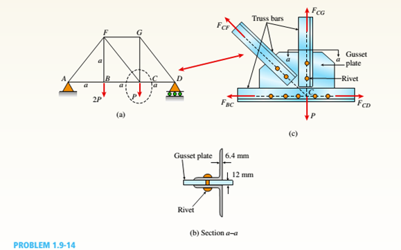
A plane truss is subjected to loads 2P and P at joints B and C, respectively, as shown in the figure part a. The truss bars are made of two L 102 X 76 X 6.4 steel angles (see Table F-5(b): cross-sectional area or the two angles, A = 2180 mm2, and figure part b) having an ultimate stress in tension equal to 390 MPa. The angles are connected to a 12-mm-thick gusset plate at C(figure part c) with 16-mm diameter rivets; assume each rivet transfers an equal share of the member force to the gusset plate. The ultimate stresses in shear and bearing for the rivet steel are 190 MPa and 550 MPa, respectively. Determine the allowable load Pallowif a safety factor of 2.5 is desired with respect to the ultimate load that can be carried. Consider tension in the bars, shear in the rivets, bearing between the rivets and gusset plate. Disregard friction between the plates the bars, and also bearing between the rivets and the and the weight of the truss itself.
The maximum load,
Answer to Problem 1.9.14P
The maximum load,
Explanation of Solution
Given:
Member forces from truss analysis:
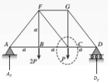
Take moment about point A as follows:
Take summation of force in the vertical direction as follows:
Apply section method for the given truss as follows:

Take moment about point F as follows:
Take moment about point B as follows:
Take summation of force in the vertical direction as follows:
Change the direction of
Consider point D as an equilibrium point which is shown below:
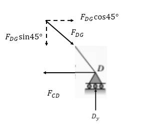
Take summation of force in the vertical direction as follows:
Take summation of force in the horizontal direction as follows:
Consider point G as follows:
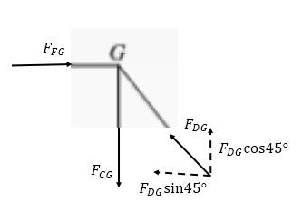
Take summation of force in the vertical direction as follows:
Thus, all the forces are:
The above force is less than the maximum force in a member. So, BC controls, since it has the largest member force for this loading.
The above area is less for one rivet in double shear.
Where,
N = number of rivets in a particular member
So, shear in rivets in CG&CD controls
Now,
Finally,
So, gusset will control over angles
So, shear in rivets controls:
Want to see more full solutions like this?
Chapter 1 Solutions
Mechanics of Materials (MindTap Course List)


- : +0 العنوان use only Two rods fins) having same dimensions, one made orass (k = 85 Wm K) and the mer of copper (k = 375 W/m K), having of their ends inserted into a furna. At a section 10.5 cm a way from furnace, the temperature of brass rod 120 Find the distance at which the ame temperature would be reached in the per rod ? both ends are ex osed to the same environment. ns 2.05 ۲/۱ ostrararrow_forwardمشر on ۲/۱ Two rods (fins) having same dimensions, one made of brass(k=85 m K) and the other of copper (k = 375 W/m K), having one of their ends inserted into a furnace. At a section 10.5 cm a way from the furnace, the temperature brass rod 120°C. Find the distance at which the same temperature would be reached in the copper rod ? both ends are exposed to the same environment. 22.05 ofthearrow_forwardThe composite wall of oven with A= 1m² as in Fig.1 consists of three materials, two of with kA = 20 W/m K and kc = 50 W/m K with thickness, LA=0.3 m, L= 0.15 m and Lc 0.15 m. The inner surface temperature T1=900 K and the outer surface temperature T4 300 K, and an oven air temperature of To=1100 K, h=25 W/m². K. Determine kɛ and the temperatures T2 and T3 also draw the thermal resistance networkarrow_forward
- Two rods (fins) having same dimensions, one made of brass (k = 85 Wm K) and the other of copper (k = 375 W/m K), having one of their ends inserted into a furnace. At a section 10.5 cm a way from the furnace, the temperature of brass rod 120°C. Find the distance at which the same temperature would be reached in the copper rod ? both ends are exposed to the same environment. Ans 22.05arrow_forwardA long wire (k-8 W/m °C.) with ro 5 mm and surface temperature Ts=180°C as shown in Fig.2. Heat is generated in the wire uniformly at a rate of 5 x10⁷ W/m³. If the energy equation is given by: d 11(77) + - =0 k r dr dr Derive an expression for T(r) and determine the temperature at the center of the wire and at r=2 mm. Air Th T KA LA T2 T3 T Fig.1 KB kc 180°C Го Fig.2arrow_forwardB: Find the numerical solution for the 2D equation below and calculate the temperature values for each grid point shown in Fig. 2 (show all steps). (Do only one trail using following initial values and show the final matrix) T₂ 0 T3 0 I need a real solution, not artificial intelligence locarrow_forward
- Can I solve this problem by calculating the initial kinetic energy with respect to G instead of A.arrow_forwardB: Find the numerical solution for the 2D equation below and calculate the temperature values for each grid point shown in Fig. 2 (show all steps). (Do only one trail using following initial values and show the final matrix) T₂ 0 T3 0 locarrow_forwardShow all work. Indicate the origin that is used for each plane. Identify the Miller indices for the following planes. N 23 1 A) X B) yarrow_forward
- the following table gives weight gain time data for the oxidation of some metal at an elevated temperature W(mg/cm2). Time (min) 4.66 20 11.7 50 41.1 175 a) determin whether the oxidation kinetics obey a linear, parabolic, or logarithmic rate expression. b) Now compute W after a time of 1000 minarrow_forwardA cylindrical specimen of aluminum is pulled in tension. Use the stress v. strain plot below for this specimen of Al to answer parts (a) - (f). Hint: Each strain increment is 0.004. Be sure to include your engineering problem solving method per the class rubric. 400 350 300 250 Stress (MPa) 200 150 100 50 Aluminum (Stress v. Strain) 0 0 0.02 0.04 0.06 0.08 Strain 0.1 0.12 0.14 0.16 a. Compute the modulus of elasticity. b. Determine the yield strength at a strain offset of 0.002. c. Determine the tensile strength of this metal. d. Compute the ductility in percent elongation. e. Compute the modulus of resilience. f. Determine the elastic strain recovery for an unloaded stress of 340 MPa.arrow_forwardConsider a single crystal of silver oriented such that a tensile stress is applied along a [112] direction. If slip occurs on a (011) plane and in a [111] direction and is initiated at an applied tensile stress of 15.9 MPa, compute the critical resolved shear stress.arrow_forward
 Mechanics of Materials (MindTap Course List)Mechanical EngineeringISBN:9781337093347Author:Barry J. Goodno, James M. GerePublisher:Cengage Learning