
Concept explainers
Videos
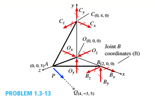
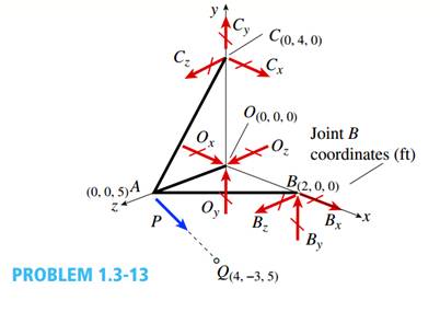
A space truss has three-dimensional pin supports at joints 0, B, and C, Load P is applied at joint A and acts toward point Q. Coordinates of all joints arc given in feet (see figure).
(a) Find reaction force components B x, B z, and Oz
(b) Find the axial force in truss member AC.
(a)
You need to determine the force components

Answer to Problem 1.3.13P
The forces are:
Explanation of Solution
Given Information:
You have following figure with all relevant information,
Draw free body diagram of joints and use equilibrium of forces to determine the unknowns.
Calculation:
Draw free body diagram as shown in the following figure,

Joint A :
The forces at joint A are,
Take equilibrium of forces at joint A in vector form,
The vector equation yields three equations in components form as below,
Solve the three equations to get
Joint O :
Consider the free body diagram again,
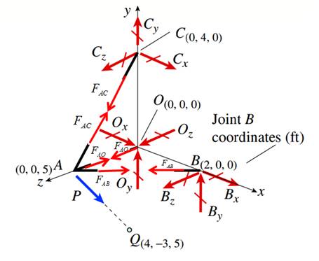
The forces at joint O are,
Take equilibrium of forces at joint O in vector form,
The vector equation yields three equations in components form as below,
Solve the equation (3) to get
Joint B :
Consider the free body diagram again,

The forces at joint B are,
Take equilibrium of forces at joint O in vector form,
The vector equation yields three equations in components form as below,
Solve the equation (3) to get
Conclusion:
Therefore the forces are:
(b)
You need to determine the member force

Answer to Problem 1.3.13P
The forces are:
Explanation of Solution
Given Information:
You have following figure with all relevant information,

Draw free body diagram of joints and use equilibrium of forces to determine the unknowns.
Calculation:
Draw free body diagram as shown in the following figure,

Joint A :
The forces at joint A are,
Take equilibrium of forces at joint A in vector form,
The vector equation yields three equations in components form as below,
Solve the three equations to get
Conclusion:
Therefore the member force in AC is:
Want to see more full solutions like this?
Chapter 1 Solutions
Mechanics of Materials (MindTap Course List)


- A space truss is restrained at joints O, A. B. and C, as shown in the figure. Load P is applied at joint A and load IP acts downward at joint C. (a) Find reaction force components Ax, By, and B. in terms of load variable P. (b) Find the axial force in truss member AB in terms of load variable P.arrow_forwardFrame ABCD carries two concentrated loads (2P at T and P at ZX see figure) and also a linearly varying distributed load on AB, Find expressions for shear force Fand moment A/at x = L/3 of beam AB in terms of peak load intensity q0, force P, and beam length variable L. Let q0= P/L.arrow_forwardA plane frame is restrained al joints A and C, as shown in the figure. Members AB and BC are pin connected at B. A triangularly distributed lateral load with a peak intensity or 90 lb/ft acts on AB. A concentrated moment is applied at joint C. (a) Find reactions at supports A and C. (b) Find internal stress resultants A', V, and \f at x = 3 ft on column AB.arrow_forward
- A space truss is restrained at joints A, B. and C, as shown in the figure. Load P acts in the +z direction at joint Band in the -z directions at joint C. Coordinates of all joints are given in terms of dimension variable L (see figure). Let P = 5 kN and L = 2 m. (a) Find the reaction force components Az and Bx. (b) Find the axial force in truss member AB.arrow_forwardSpace frame A BCD is clamped at A, except it is Free to translate in the .v direction. There is also a roller support at D, which is normal to line CDE. A triangularly distributed Force with peak intensity q0 = 75 N/m acts along AB in the positive - direction. Forces Px= 60 N and Pz = = 45 N are applied at joint C, and a concentrated moment My = 120 N . m acts at the mid-span of member BC. (a) Find reactions at supports A and I). (b) Find internal stress resultants N. E’I T, and .11 at the mid-height of segment AB.arrow_forwardFind support reactions at A and D and then calculate the axial force N, shear force V, and bending moment M at mid-span of AB. Let L = 14 ft, q0 = 12 lb/ft, P = 50 lb. and = 300 lb-ft.arrow_forward
- A soccer goal is subjected to gravity loads (in the - z direction, w = 73 N/m for DG, BG, and BC; w = 29 N/m for all other members; see figure) and a force F = 200 N applied eccentrically at the mid-height of member DG. Find reactions at sup ports C, D, and H.arrow_forwardSegments A B and BCD of beam A BCD are pin connected at x = 4 m. The beam is supported by a sliding support at A and roller supports at C and D (see figure). A triangularly distributed load with peak intensity of SO N/m acts on EC. A concentrated moment is applied at joint D. (a) Find reactions at supports A, C, and D. (b) Find internal stress resultants N, Y, and Mat x = 5m. (c) Repeat parts (a) and (b) for die case of the roller support at C replaced by a linear spring of stiffness kr™ 200 kN/m (see figure).arrow_forwardA beam ABCD with a vertical arm CE is supported as a simple beam al A and D (see figure part a). A cable passes over a small pulley that is attached to the arm at E. One end of the cable is attached to the beam at point B. (a) What is the force P in the cable if the bending moment in the beam just lo the left of point C is equal numerically to 640 lb-ft? Note: Disregard the widths of the beam and vertical arm and use centerline dimensions when making calculations. (b) Repeat part (a) if a roller support is added at C and a shear release is inserted just left of C (see figure part b).arrow_forward
- Find support reactions at A and D and then calculate the axial force N. shear force 1 and bending moment 11 at mid-span of column BD. Let L = 4 m, q0 = 160N/m, P = 200N, and M0= 380 N .m.arrow_forwardA foot bridge on a hiking trail is constructed using two timber logs each having a diameter d = 0.5 m (see figure a). The bridge is simply supported and has a length L = 4 m. The top of each log is trimmed to form the walking surface (see Fig, b)LA simplified model of the bridge is shown in Fig. g. Each log must carry its own weight w = 1.2 kN/m and the weight (P = 850 N) of a person at mid-span, (see Fig. b). Determine the maximum tensile and compressive stresses in the beam (Fig, b) due to bending. If load h is unchanged, find the maximum permissible value of load ... if the allowable normal stress in tension and compression is 2.5 M Pa.arrow_forwardA T-frame structure is torn posed of a prismatic beam ABC and a nonprismatic column DBF. The beam and the column have a pin support at .A and D, respectively. Both members are connected with a pin at B. The lengths and properties of the members are shown in the figure. Find the vertical displacement of the column at points F and B. Plot axial force (AFD) and axial displacement (ADD) diagrams For column DBF.arrow_forward
 Mechanics of Materials (MindTap Course List)Mechanical EngineeringISBN:9781337093347Author:Barry J. Goodno, James M. GerePublisher:Cengage Learning