
Concept explainers
Videos
We are given
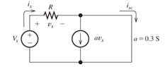
Figure T1.5
Want to see the full answer?
Check out a sample textbook solution
Chapter 1 Solutions
Electrical Engineering: Principles & Applications Plus Mastering Engineering with Pearson eText -- Access Card Package (7th Edition)
Additional Engineering Textbook Solutions
Electric Motors and Control Systems
Introductory Circuit Analysis (13th Edition)
ELECTRICITY FOR TRADES (LOOSELEAF)
Electronics Fundamentals: Circuits, Devices & Applications
Electric machinery fundamentals
Loose Leaf for Engineering Circuit Analysis Format: Loose-leaf


- In the figure, ε = 119 V, R₁ = 9.01 Q, R₂ = 29.2 Q, R3 = 38.3 Q, and L = 2.34 H. Immediately after switch S is closed, what are (a) i₁ and (b) i₂? (Let currents in the indicated directions have positive values and currents in the opposite directions have negative values.) A long time later, what are (c) i₁ and (d) i2? The switch is then reopened. Just then, what are (e) i₁ and (f) i₂? A long time later, what are (g) i₁ and (h) i₂? (a) Number (b) Number (c) Number i Units Units Units R₁ R$ Ro L elearrow_forwardReferring to Figure Q1, switch S1 is closed at t= 0 and switch S2 is closed at t= 7s. Find the value of current i (t) at t= 3s. t= 0 10 Ω a S2 Spt= 7 30 V 8Ω 4 H 20 V Figure Q1 O A. 2.7A О В. ЗА о с. 2.5A O D. 2.4A O E. OAarrow_forwardFind the currents I,, I,, and I, in the circuit shown in the figure. (Use Ɛ = 15.00 V.) %3D A circuit containing different branches. of 4.0 N C 6.0 N 10.0 V a d 2.0 N SOLUTION Conceptualize Imagine physically rearranging the circuit while keeping it electrically the same. Can you rearrange it so that it consists of simple series or parallel combinations of resistors? You should find that you cannot. (If the 10.0 V battery were removed and replaced by a wire from b to the 6.0 N resistor, the circuit would consist of only series and parallel combinations.) Categorize We cannot simplify the circuit by the rules associated with combining resistances in series and in parallel. Therefore, this problem is one in which we must use ---Select--- Analyze We arbitrarily choose the directions of the currents as labeled in the figure. According to the label, the current through the 6.0 Q resistor is in which direction in the figure? O to the right O to the left O downward O upward Apply Kirchhoff's…arrow_forward
- Q1) For the following circuit, sketch the output for one cycle of the input voltage. Use a constant-voltage model with VD,=0.7V and. also write an expression for Vo(t). R1 = 10 k2 + R2 = 10 k2 Ą D2 v = 6 sin wt D1 vo + V2 = 4 V V1 = 2 V · +arrow_forwardQ1. Figure-Q1 shows an R-L electrical network. t = 0 R1 L1 i x i2 L2 20 Ω 0.5 H 1.0 H * R3 10 Ω *R2 e(t) = 200 V. Figure-Q1 a. Derive the differential equation for each loop of the circuit in terms of i,, iz and e. b. Derive the expression for i2(t).arrow_forwardConsider the circuit shown in the figure below. (Let R₁ = 6.00 0, R₂ = 8.00 0, and 8 - 10.0 V.) 2.000 W 10.00 www 5.000 www & 16 (a) Find the voltage across R₁. (b) Find the current in R₁. R₂ wwwarrow_forward
- QUESTION 5 What is the steady-state current across R₁ in A given the supply voltage of 8 V is a applied at t=0? Let R1 = 2202, R2 = 350, and C = 0.00017 F. Use scientific notation with 3 significant figures. Omit units. R₁₁ C= R₂arrow_forwardAnswers are a) w= 0.829 and Ke 7.5 b) G.(s)= (4.263s²+4.5s+1.188)/s Please explain... fastlyarrow_forwardThe RL network in Figure 1.170 has been at rest for a long period of time with the switch Si open. At time t = 0, Sı is closed as indicated on the schematic. Using the values shown, you are asked to do the following. (a) Calculate values for the inductor current iL(t) at t = 0* and t=∞ (i.e., iL(0*) and İL(0)), and the network time constant t in seconds. (b) Apply these values to generate and write fully the complete time-domain expression for iL(t) found from the solution of the network describing equation. (c) Calculate the value for the rise time t; in seconds. Jg2 S1 t = 0 L 18µH lell 9mA R1 2KΩ İL(t) Eg1 12v R2 6ΚΩ R3 3ΚΩ Figure 1.170 RL network driven by a voltage and current sourcearrow_forward
- Find vet) for t 2 0 for the circuit of Figure 2. Assume steady-state conditions exist before t = 0. 10 Ω K= 0 1H 10 1/4 FUc 20 V Figure 2arrow_forwardFor the circuit below with switch U1 closing at time t=0 and the initial voltage across Cl equal zero, find the transient response voltage across the resistor R1: (Provide your calculations and reasoning for your answer.) C1 1 U1 20u V1 20Vde R1 100karrow_forwardWe are given i 4 = 2 A for the circuit of Figure T1.6. Use Ohm’s law, KCL, and KVL to find the values of i 1, i 2, i 3 and vs.arrow_forward
 Introductory Circuit Analysis (13th Edition)Electrical EngineeringISBN:9780133923605Author:Robert L. BoylestadPublisher:PEARSON
 Delmar's Standard Textbook Of ElectricityElectrical EngineeringISBN:9781337900348Author:Stephen L. HermanPublisher:Cengage Learning
 Programmable Logic ControllersElectrical EngineeringISBN:9780073373843Author:Frank D. PetruzellaPublisher:McGraw-Hill Education
 Fundamentals of Electric CircuitsElectrical EngineeringISBN:9780078028229Author:Charles K Alexander, Matthew SadikuPublisher:McGraw-Hill Education
 Electric Circuits. (11th Edition)Electrical EngineeringISBN:9780134746968Author:James W. Nilsson, Susan RiedelPublisher:PEARSON
 Engineering ElectromagneticsElectrical EngineeringISBN:9780078028151Author:Hayt, William H. (william Hart), Jr, BUCK, John A.Publisher:Mcgraw-hill Education,