
Electrical Engineering: Principles & Applications Plus Mastering Engineering with Pearson eText -- Access Card Package (7th Edition)
7th Edition
ISBN: 9780134712871
Author: Allan R. Hambley
Publisher: PEARSON
expand_more
expand_more
format_list_bulleted
Concept explainers
Videos
Textbook Question
Chapter 1, Problem 1.1PT
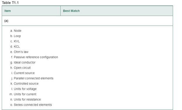
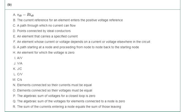
Match each entry in Table T1.1(a) with the best choice from the list given in Table T1.1(b). [Items in Table T1.1(b) may be used more than once or not at all.]
Expert Solution & Answer
Want to see the full answer?
Check out a sample textbook solution
Students have asked these similar questions
how do I do question 1.1?
Make a table of values that shows all calculations with the switch on verses the switch off. Make sure you use proper nomenclature like R1...VR1…PR1… IRb…IRc…IR1…etc.
Please show in details how do do this
Chapter 1 Solutions
Electrical Engineering: Principles & Applications Plus Mastering Engineering with Pearson eText -- Access Card Package (7th Edition)
Ch. 1 - Broadly speaking, what are the two main objectives...Ch. 1 - Prob. 1.2PCh. 1 - List eight subdivisions of electrical engineering.Ch. 1 - Prob. 1.4PCh. 1 - Prob. 1.5PCh. 1 - In the fluid-flow analogy for electrical circuits,...Ch. 1 - The charge of an electron is 1.601019C . A current...Ch. 1 - The ends of a length of wire are labeled a and b....Ch. 1 - The circuit element shown in Figure P1.9 has v=12V...Ch. 1 - Prob. 1.10P
Ch. 1 - The net charge through a cross section of a...Ch. 1 - The current through a particular circuit element...Ch. 1 - The current through a given circuit element is...Ch. 1 - The net charge through a cross section of a...Ch. 1 - A copper wire has a diameter of 2.05 mm and...Ch. 1 - A certain lead acid storage battery has a mass of...Ch. 1 - A circuit element having terminals a and b has...Ch. 1 - An electron moves through a voltage of 9 V from...Ch. 1 - A typical “deep-cycle” battery (used for electric...Ch. 1 - Define the term passive reference configuration....Ch. 1 - Compute the power for each element shown in Figure...Ch. 1 - The terminals of an electrical device are labeled...Ch. 1 - The terminals of a certain battery are labeled a...Ch. 1 - The element shown in Figure P1.24 I has v(t)=10V...Ch. 1 - The current and voltage of an electrical device...Ch. 1 - Suppose that the cost of electrical energy is...Ch. 1 - Figure P1.27 shows an ammeter (AM) and voltmeter...Ch. 1 - Repeat Problem P1.27 with the meters connected as...Ch. 1 - A certain type of D-cell battery that costs $0.50...Ch. 1 - The electronics aboard a certain sailboat consume...Ch. 1 - What s a node in an electrical circuit? Identify...Ch. 1 - State Kirchhoff’s current law.Ch. 1 - Two electrical elements are connected in series....Ch. 1 - Suppose that in the fluid-flow analogy for an...Ch. 1 - Identify elements that are in series in the...Ch. 1 - Consider the circuit shown in Figure P1.36. Which...Ch. 1 - Use KCL to find the values of ia, ic , and id for...Ch. 1 - Find the values of the other currents in Figure...Ch. 1 - Prob. 1.39PCh. 1 - State Kirchhoff’s voltage law.Ch. 1 - Consider the circuit shown in Figure P1.36. Which...Ch. 1 - Use KVL to solve for the voltages va , vb, and vc...Ch. 1 - Solve for the other voltages shown in Figure P1.43...Ch. 1 - Use KVL and KCL to solve for the labeled currents...Ch. 1 - Identify elements that are in parallel in Figure...Ch. 1 - Points a, b, c, and d appear in a certain circuit....Ch. 1 - In your own words, define an ideal conductor; an...Ch. 1 - Name four types of dependent sources and give the...Ch. 1 - State Ohm’s law, including references.Ch. 1 - Draw a circuit that contains a 5 resistance, a...Ch. 1 - Repeat Problem P1.50, placing all three elements...Ch. 1 - The resistance of a certain copper wire is 0.5. ....Ch. 1 - Draw a circuit that contains a 5 resistor, a 10-V...Ch. 1 - Draw a circuit that contains a 5 resistor, a 10-V...Ch. 1 - A power of 100 W is delivered to a certain...Ch. 1 - The voltage across a 10 resistor is given by...Ch. 1 - The voltage across a 10 resistor is given by...Ch. 1 - A certain wire has a resistance of 0.5 . Find the...Ch. 1 - Plot i versus v to scale for each of the parts of...Ch. 1 - Which of the following are self-contradictory...Ch. 1 - Consider the circuit shown in Figure P1.61. Find...Ch. 1 - Consider the circuit shown in Figure P1.62. Find...Ch. 1 - Consider the circuit shown in Figure P1.63. Find...Ch. 1 - Consider the circuit shown in Figure P1.64. Use...Ch. 1 - Determine the value of Ix in the circuit shown in...Ch. 1 - Consider the circuit shown in Figure P1.66. Figure...Ch. 1 - Prob. 1.67PCh. 1 - Consider the circuit shown in Figure P1.68. Figure...Ch. 1 - Solve for the currents shown in Figure P1.69....Ch. 1 - The circuit shown in Figure P1.70 contains a...Ch. 1 - Determine the value of vx and iy in the circuit...Ch. 1 - A 10-V independent voltage source is in series...Ch. 1 - A 10-V independent voltage source is in parallel...Ch. 1 - Consider the circuit shown in Figure P1.74. Figure...Ch. 1 - The circuit shown in Figure P1.75 contains a...Ch. 1 - For the circuit shown in Figure P1.76, solve for...Ch. 1 - For the circuit shown in Figure P1.77, solve for...Ch. 1 - Match each entry in Table T1.1(a) with the best...Ch. 1 - Prob. 1.2PTCh. 1 - The circuit of Figure T1.3 has I1=3A , I2=1A ,...Ch. 1 - The circuit shown in Figure T1.4 has Vs=12V ,...Ch. 1 - We are given Vs=15V , R=10 , and =0.3S for the...Ch. 1 - We are given i4=2A for the circuit of Figure T1.6....
Additional Engineering Textbook Solutions
Find more solutions based on key concepts
Identify the type of input and output configuration for each diff-amp in Figure 18-35.
Electronics Fundamentals: Circuits, Devices & Applications
How many coulombs do 93.8 1016 electrons represent?
Principles Of Electric Circuits
Assume a telephone signal travels through a cable at two-thirds the speed of light. How long does it take the s...
Electric Circuits (10th Edition)
Write the nodal equations for the network of Fig. 8.137 using the general approach. Find the nodal voltages usi...
Introductory Circuit Analysis (13th Edition)
Analog Voltmeter Design Figure P2-98(a) shows a voltmeter circuit consisting of a D'Arsonval meter, two series ...
ANALYSIS+DESIGN OF LINEAR CIRCUITS(LL)
With respect to the circuit in Fig. 5.90, (a) employ Thévenin’s theorem to determine the equivalent network see...
Loose Leaf for Engineering Circuit Analysis Format: Loose-leaf
Knowledge Booster


Learn more about
Need a deep-dive on the concept behind this application? Look no further. Learn more about this topic, electrical-engineering and related others by exploring similar questions and additional content below.Similar questions
- Q1 (i) What is an LVDT and what is it used for? (ii) Describe the construction features of an LVDT. Q2 (i) What is a strain gauge and what is it used for? (ii) What is the principle of operation of a strain gauge? (iii) Describe some applications of strain gauges.arrow_forwardwrite the name of counter type on the side. this counter what numbers count and whats the mod(....) level(NEED A NEAT HANDWRITTEN SOLUTION ONLY OTHERWISE DOWNVOTE)arrow_forwardClick Submit to complete this assessment. Question 10 Extrinsic semiconductors are having more charge carriers than intrinsic semiconductor. True False A Click Submit to complete this assessment. MacBook Proarrow_forward
- PLS PLS SHOW COMPLETE SOLUTION AND WRITE LEGIBLY. DRAW CIRCUIT DIAGRAM. PLS PLSS SHOW HOW THE EQUATIONS REDUCED TO NEEDED.arrow_forwardWhat will be the result if the difference between true value and measured value decreasing in the measurement system? O a. The accuracy is observed to be constant O b. The accuracy is observed to be increasing O C. The accuracy is observed to be decreasing Od. The accuracy is observed to be infinite 40 ENG Type here to se.arrow_forward(01) DC Si Diode Circuit. (Course: Electronic Devices and Circuit Theory) -Use Equation Operators or write it down on paper/digital paper. -Redraw and Apply. -You can add //comments for a better understanding. -Please answer without abbreviation. -Make it clean and clear typing/writing. Thank you.arrow_forward
- Can someone please verify both circuits components are within their min/max limits? I have a hard time understanding the data sheets Will upvote! Same components used for both. Table with operating voltage and current attachedarrow_forwardI opened a broken Coin Pusher Arcade game to fix, and I saw a burned IC. Between Microprocessor and Microcontroller, what kind of IC do you think is that? And why?arrow_forwardCan you draw the circuit for this ? Thank you ?arrow_forward
- In the circuit given in the figure, calculate the IC current by full analysis, as R1 = 18.10Kohm, R2 = 67.58Kohm, RC = 1.08Kohm, RE = 3.23Kohm, VCC = 14.00V, Beta = 241.00. When making your transactions, 2 steps will be taken after the point. Select the closest option according to +/- 10% margin of error. There is only one correct answer to the question. RE C1 R2 Q1 C2 Ry ŽRC R1 1.54mA O 2.67mA O 0.77mA 3.11mA 1.98mA O 1.75mAarrow_forwardinterpret the data, describe the graph,describe the curve.arrow_forwardI have an O Gauge track and would like to convert it into a “sensored” track. Additionally, I would like to connect that track to an ESP-WROOM-32 board that should flash an LED whenever the track detects a non-moving train. Please list all the components (and how many of each) needed. Also, what’s the procedure for connecting the components?arrow_forward
arrow_back_ios
SEE MORE QUESTIONS
arrow_forward_ios
Recommended textbooks for you

What is a Thyristor? - A Galco TV Tech Tip; Author: GalcoTV;https://www.youtube.com/watch?v=LBb_Qz7J3zA;License: Standard Youtube License