International Edition---engineering Mechanics: Statics, 4th Edition
4th Edition
ISBN: 9781305501607
Author: Andrew Pytel And Jaan Kiusalaas
Publisher: CENGAGE L
expand_more
expand_more
format_list_bulleted
Question

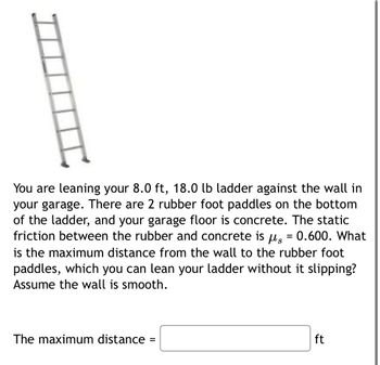
Transcribed Image Text:You are leaning your 8.0 ft, 18.0 lb ladder against the wall in
your garage. There are 2 rubber foot paddles on the bottom
of the ladder, and your garage floor is concrete. The static
friction between the rubber and concrete is μs = 0.600. What
is the maximum distance from the wall to the rubber foot
paddles, which you can lean your ladder without it slipping?
Assume the wall is smooth.
The maximum distance
=
ft
Expert Solution
This question has been solved!
Explore an expertly crafted, step-by-step solution for a thorough understanding of key concepts.
Step by stepSolved in 2 steps with 5 images

Knowledge Booster
Similar questions
- Open with Google Docs The homogeneous semicylinder rests on a horizontal surface and is subjected to the force P applied to a cord firmly attached to its periphery. The force P is slowly increased and kept normal to the flat surface of the semicylinder. If slipping is observed just as 0 reaches 40°, determine the coefficient of static fric- tion u, and the value of P when slipping occurs. B 3.arrow_forwardPlease show each and every steps , do not write the equations directly.arrow_forwarddo allarrow_forward
- I need to solved this question quickly pleasearrow_forwardThe diameter of two pulleys are (0.3m)and (0.2m), center distance (1m).if we use open belt drive. Determine: 1- the length of V- belt (2ß = 60°). 2- the contact angle between belt and smaller pulley. 3- the horse power, if the smaller pulley turn with speed (400r.p.m) and the tension force in tight side (T1=90ON), coefficient of friction u=0.3 4- the speed of large pulley.arrow_forwardWhat is the normal force between the crate and the wedge? What is the smallest force P needed to pull out the wedge?arrow_forward
- Physics Problem about Torque and forces. Show the location of the axis of rotation and r for each force that produces torque in the diagram. Also, check calculations, I am off by 1 degree.arrow_forwardTorque Problem The diagram below shows the lower leg being held in a stationary. The torque acting to turn the leg in a clockwise direction is being generated by the weight of the leg and the weight of a barbel attached to the ankle. Using the information provided calculate the magnitude of the quadriceps force. LOWER LEG IN ANGULAR EQUILIBRIUM 15° Quadriceps muscle force 0.05m 0.14 m 50° 0.30m 90 Newtons 120 Newtons Show your calculations step by step here. Includes diagrams and short comments to explain your approach to solving the problem.arrow_forwardAn engineer trying to determine whether her crane will tip over when attempting to lift a 13K load. Her crane has a 15K chassis and 35K counterweight. Assume all other parts of the crane have negligible weight. Answer all questions relative to the rotation point. How much torque is caused by the load? How much torque is caused by the chassis? How much torque is caused by the counterweight? What is the normal force on the rear (right) outriggers? What is the normal force on the front (left) outriggers? *each box in picture = 5 ftarrow_forward
arrow_back_ios
SEE MORE QUESTIONS
arrow_forward_ios
Recommended textbooks for you
 International Edition---engineering Mechanics: St...Mechanical EngineeringISBN:9781305501607Author:Andrew Pytel And Jaan KiusalaasPublisher:CENGAGE L

International Edition---engineering Mechanics: St...
Mechanical Engineering
ISBN:9781305501607
Author:Andrew Pytel And Jaan Kiusalaas
Publisher:CENGAGE L