Elements Of Electromagnetics
7th Edition
ISBN: 9780190698614
Author: Sadiku, Matthew N. O.
Publisher: Oxford University Press
expand_more
expand_more
format_list_bulleted
Question

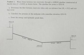
Transcribed Image Text:Problem 1. Water flows between two reservoirs through a 4,000-ft pipeline constructed of
ductile iron (f= 0.019) as shown below. The pipeline low point is 125.0 ft.
a. Determine the flow between reservoirs when only an entrance loss (Ke = 0.5) and exit
loss occur.
b. Calculate the pressure at the midpoint with centerline elevation 125.0 ft.
c. Draw the energy and hydraulic grade lines.
255.0 ft
8 inch 2000 ft
8 inch 2000 ft
125.0 ft
140.0 ft
Expert Solution
This question has been solved!
Explore an expertly crafted, step-by-step solution for a thorough understanding of key concepts.
Step by stepSolved in 2 steps with 2 images

Knowledge Booster
Similar questions
- 8.) Assume that the 57 liters per second of oil (P = 860 kg/m3) is pumped through a 300 mm diameter pipeline of cast iron. If each pump produces 685kPa, how far apart can they be placed? (Assume f = 0.031) Answer: 23.718 km Subject: fluid mechanic Lesson: *Conservation of Energy *Fluid Flow in Pipesarrow_forwardCan you please solve correctlyarrow_forward12. Points A and B are 3000 ft apart along a 10-in. new steel pipe. B is 220 ft higher than A. With a flow of 3.2 efs of water from A to B, what pressure must be maintained at A if the pressure at B is to be 50 Ib per sq in.? Answer should be: 164 lb per sq. inch Show your handwritten solution.arrow_forward
- 8. A pumped fluid distribution system is being designed to deliver 400 gal/min of water to a cooling system in a power generation plant. Use the figure below to make an initial selection of Schedule 40 pipe sizes for the suction and discharge lines for the system. Also, solve for the actual average velocity of flow for each pipe. DN (mm) NPS (in) 250 200 150 - 125 - Suction lines 100 - 90 - 3 65 - 2 50 Discharge lines 40 32E 25 E 15 20 200 400 600 800 1000 2000 4000 6000 8000 10000 10 100 Volume Flow Rate, Q (gal/min) 6 8 10 ++++ 15 20 25 30 40 +++++++++ ++++++++++++ 60 80 100 150 200 300 400 500600 800 1000 1200 2000 Volume Flow Rate, Q (m/h)arrow_forwardAnswer the following: a.) What is the velocity inside the pipe? b.) Compute for the Reynolds numberarrow_forwardSubject : Fluid mechanics Solve both a and b Help me urgentarrow_forward
- A 400 gpm piping system is composed of the following pipes and fittings. Using the chart; Determine the Following: a. Equivalent length at suction in ft b. Equivalent length at discharge in ft c. Total friction loss in the installation, in ft. Suction side (4.5” Փ) Length of straight pipe 210 ft Long sweep elbow 5 pcs Standard Tee 2 pcs Globe valve 1 pc Checked valve 1 pc Gate valve (fully open) 1 pc Discharge side (4.0” Փ) Straight pipe 200 ft Standard elbow 4 pcs Standard Tee 3 pcs Gate valve (fully open) 1 pcarrow_forwardCan you do Part D of this question. Parts A - C have already been done.arrow_forward7. A large tank is partly filled with water, the air space above being under pressure. A 2" hose connected to the tank discharges on the roof of a building 50 ft above the level in the tank. The friction loss is 18 ft. What air pressure must be maintained in the tank to deliver 0.436 cfs on the roof ?arrow_forward
- Problem 5: Energy Equation This question tests your ability to recognize the components of the energy equation: Ply+z+V²/(2g) = constant. On your submission, write each of the following six concepts, then write the relevant component (or "none"): elevation head P/Y pressure head P/Y dynamic head P/y P/Y neglect for steady flow neglect for horizontal flow neglect for open channel flow Ply P/Y Z V²/(2g) V²/(2g) v²/(2g) Z V²/(2g) V²/(2g) V²/(2g) Z Z N N none none none none none nonearrow_forwardPlease don't provide handwritten solution ....arrow_forwardFor the pipe system shown. Assume n = 0.013 for all pipes. Neglect minor losses. 1. Compute the head loss from A to B in terms of Q. a. 0.056Q2 b. 0.029Q2 c. 0.016Q2 d. 0.096Q2 2. Assuming Q = 12 cfs, compute the head loss of pipe CD. a. 15.78 ft b. 13.02 ft c. 18.56 ft d. 24.56 ft 3. Assuming Q = 12 cfs, compute the total head loss from A to D. a. 47.786 ft b. 56.673 ft c. 89.451 ft d. 32.562 ftarrow_forward
arrow_back_ios
SEE MORE QUESTIONS
arrow_forward_ios
Recommended textbooks for you
 Elements Of ElectromagneticsMechanical EngineeringISBN:9780190698614Author:Sadiku, Matthew N. O.Publisher:Oxford University Press
 Mechanics of Materials (10th Edition)Mechanical EngineeringISBN:9780134319650Author:Russell C. HibbelerPublisher:PEARSON
 Thermodynamics: An Engineering ApproachMechanical EngineeringISBN:9781259822674Author:Yunus A. Cengel Dr., Michael A. BolesPublisher:McGraw-Hill Education
 Control Systems EngineeringMechanical EngineeringISBN:9781118170519Author:Norman S. NisePublisher:WILEY
 Mechanics of Materials (MindTap Course List)Mechanical EngineeringISBN:9781337093347Author:Barry J. Goodno, James M. GerePublisher:Cengage Learning
 Engineering Mechanics: StaticsMechanical EngineeringISBN:9781118807330Author:James L. Meriam, L. G. Kraige, J. N. BoltonPublisher:WILEY

Elements Of Electromagnetics
Mechanical Engineering
ISBN:9780190698614
Author:Sadiku, Matthew N. O.
Publisher:Oxford University Press

Mechanics of Materials (10th Edition)
Mechanical Engineering
ISBN:9780134319650
Author:Russell C. Hibbeler
Publisher:PEARSON

Thermodynamics: An Engineering Approach
Mechanical Engineering
ISBN:9781259822674
Author:Yunus A. Cengel Dr., Michael A. Boles
Publisher:McGraw-Hill Education

Control Systems Engineering
Mechanical Engineering
ISBN:9781118170519
Author:Norman S. Nise
Publisher:WILEY

Mechanics of Materials (MindTap Course List)
Mechanical Engineering
ISBN:9781337093347
Author:Barry J. Goodno, James M. Gere
Publisher:Cengage Learning

Engineering Mechanics: Statics
Mechanical Engineering
ISBN:9781118807330
Author:James L. Meriam, L. G. Kraige, J. N. Bolton
Publisher:WILEY