
Elements Of Electromagnetics
7th Edition
ISBN: 9780190698614
Author: Sadiku, Matthew N. O.
Publisher: Oxford University Press
expand_more
expand_more
format_list_bulleted
Related questions
Question
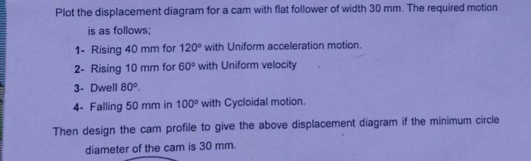

Transcribed Image Text:Plot the displacement diagram for a cam with flat follower of width 30 mm. The required motion
is as follows;
1- Rising 40 mm for 120° with Uniform acceleration motion.
2- Rising 10 mm for 60° with Uniform velocity
3- Dwell 80°.
4- Falling 50 mm in 100° with Cycloidal motion.
Then design the cam profile to give the above displacement diagram if the minimum circle
diameter of the cam is 30 mm.
Expert Solution
This question has been solved!
Explore an expertly crafted, step-by-step solution for a thorough understanding of key concepts.

Step by stepSolved in 2 steps with 1 images

Knowledge Booster

Similar questions
- Plot the displacement diagram for a cam with roller follower of diameter 10 mm. The required motion is as follows; 1- Rising 60 mm in 135° with uniform acceleration and retardation motion. 2- Dwell 90° 3- Falling 60 mm for 135° with Uniform acceleration-retardation motion. Then design the cam profile to give the above displacement diagram if the minimum circle diameter of the cam is 50 mm.arrow_forwardmotion is as follows; 1- Dwell 45°. Plot the displacement diagram for a cam with flat follower of width 14 mm. The required 2- Rising 60 mm in 90° with Simple Harmonic Motion. 3- Dwell 90°. 4- Falling 60 mm for 90° with Simple Harmonic Motion. 5- Dwell 45°. Then design the cam profile to give the above displacement diagram if the minimum circle diameter of the cam is 50 mm.arrow_forwardA cam drive is used for a mechanism incorporated in a shoe-sewing machine. The cam follower must rise outward 0.5 in. with cycloidal motion in 0.7 s, dwell for 0.2 s, fall 0.25 in. with cycloidal motion in 0.5 s, dwell for 0.2 s, fall 0.25 in. with cycloidal motion in 0.5 s and then repeat the sequence. Determine the required speed of the cam and graphically plot a follower displacement diagram.arrow_forward
- A cam drive is used for a mechanism incorporated in a shoe-sewing machine.The cam follower must rise outward 0.5 in. with cycloidal motion in 0.7 s, dwellfor 0.2 s, fall 0.25 in. with cycloidal motion in 0.5 s, dwell for 0.2 s, fall 0.25 in. withcycloidal motion in 0.5 s and then repeat the sequence. Determine therequired speed of the cam and graphically plot a follower displacementdiagram.arrow_forwardWe need correct answer and proper presentation answerarrow_forwardso A 4 I need a detailed drawing with explanation し i need drawing in solution motion is as follows; 1- Dwell 45°. Plot the displacement diagram for a cam with flat follower of width 14 mm. The required 2- Rising 60 mm in 90° with Simple Harmonic Motion. 3- Dwell 90°. 4- Falling 60 mm for 90° with Simple Harmonic Motion. 5- Dwell 45°. cam is 50 mm. Then design the cam profile to give the above displacement diagram if the minimum circle diameter of the か ---2-125 750 x2.01 98Parrow_forward
- Design a cam in non dimensional form consisting of 5 sections, each having the following characteristics: Determine equations for the cam profile for each section and box your answers for clarity. Hint: For each segment write the boundary conditions and apply them to the corresponding equation. Segment 1: (0 < y <) Has a cubic profile: Y = Ay³ + By² + Cy + D Starts from zero Dwells at zero Rises to the height of 4/3 Dwells at the height of 4/3 Segment II: (< y < 1) Dwells at the height of 4/3: Segment III: (1 < y <¹) Has a parabolic profile : Y = Ay² + By + C Starts from the height of 4/3 Dwells at the height of 4/3 Declines to the height of 1 Segment IV: (< <) Has a linear motion: Y = 4y - B Starts from the height of 1 Segment V: (arrow_forward1. A cam must rise in 3 seconds at constant velocity of 0.25 in/sec in the first segment. Then the follower must return to the zero position in 5 seconds with a full return cycloidal motion and then dwell for 3 seconds in segment 3. The final segment will be a full rise cycloidal motion. The total cycle time is 12 seconds, and the maximum height is in the first segment. Full return cycloidal motion 1 y = L + sin 2π Full rise cycloidal motion y = L sin Determine the following: The cam angular velocity. b. The cam rotation segment widths, B1 c. The lift (height) of the constant velocity segment. а. B4 , in degrees. Round off to nearest degree. d. The height at 0 = 180° е. The peak cam linear velocity V(t)peak with zero angular acceleration in segment 4.arrow_forwardA cam drive is required for a shaker platform. This platform is used to test the shipping-worthiness of packaged items. The cam follower must rise outward 1.0 in. with contant acceleration in 0.7 sec, dwell for 0.2 sec, fall with constant acceleration in 0.5 sec, and then repeat the sequence. Determine the following for the given problems: 1. Calculate the time for a full cycle 2. Calculate the required rotational speed of the cam 3. Determine the cam rotation for each follower motion interval 4. Plot the displacement diagramarrow_forward
- A cam is used to operate a platform that repeatedly lifts boxes for a height of 40 mm as shown. One cycle of the cam has the following motion requirements: Rise to 40 mm in 1.5 s, Dwell for 0.25 s, Fall for 20 mm in 1 s; Dwell for 0.25 s; Fall a further 20 mm in 1s and the cycle repeats after this. The required speed of cam is rpm and the angle turned by cam during the Rise motion is degrees. *Write your answer only as numbers, DO NOT add any text 40 mmarrow_forwardDesign a single-dwell cam to move a follower from 0 to 2 inches in 60 deg, fall 2 inches in 90 deg, and dwell for the remainder. The total cycle must take 2 seconds. Use the polynomial method to design s v a j functions. Plot the s v a j diagrams.arrow_forwardI need a detailed drawing with explanation so Solle 4 يكا Pax Pu + 96** motion is as follows; 1- Dwell 45°. Plot the displacement diagram for a cam with flat follower of width 14 mm. The required 2- Rising 60 mm in 90° with Simple Harmonic Motion. 3- Dwell 90°. 4- Falling 60 mm for 90° with Simple Harmonic Motion. 5- Dwell 45°. cam is 50 mm. Then design the cam profile to give the above displacement diagram if the minimum circle diameter of the 55 ---20125 750 X 2.01 1989arrow_forward
arrow_back_ios
SEE MORE QUESTIONS
arrow_forward_ios
Recommended textbooks for you
- Elements Of ElectromagneticsMechanical EngineeringISBN:9780190698614Author:Sadiku, Matthew N. O.Publisher:Oxford University Press
 Mechanics of Materials (10th Edition)Mechanical EngineeringISBN:9780134319650Author:Russell C. HibbelerPublisher:PEARSON
 Thermodynamics: An Engineering ApproachMechanical EngineeringISBN:9781259822674Author:Yunus A. Cengel Dr., Michael A. BolesPublisher:McGraw-Hill Education
  Control Systems EngineeringMechanical EngineeringISBN:9781118170519Author:Norman S. NisePublisher:WILEY
 Mechanics of Materials (MindTap Course List)Mechanical EngineeringISBN:9781337093347Author:Barry J. Goodno, James M. GerePublisher:Cengage Learning
 Engineering Mechanics: StaticsMechanical EngineeringISBN:9781118807330Author:James L. Meriam, L. G. Kraige, J. N. BoltonPublisher:WILEY
Elements Of Electromagnetics
Mechanical Engineering
ISBN:9780190698614
Author:Sadiku, Matthew N. O.
Publisher:Oxford University Press
Mechanics of Materials (10th Edition)
Mechanical Engineering
ISBN:9780134319650
Author:Russell C. Hibbeler
Publisher:PEARSON
Thermodynamics: An Engineering Approach
Mechanical Engineering
ISBN:9781259822674
Author:Yunus A. Cengel Dr., Michael A. Boles
Publisher:McGraw-Hill Education
Control Systems Engineering
Mechanical Engineering
ISBN:9781118170519
Author:Norman S. Nise
Publisher:WILEY
Mechanics of Materials (MindTap Course List)
Mechanical Engineering
ISBN:9781337093347
Author:Barry J. Goodno, James M. Gere
Publisher:Cengage Learning
Engineering Mechanics: Statics
Mechanical Engineering
ISBN:9781118807330
Author:James L. Meriam, L. G. Kraige, J. N. Bolton
Publisher:WILEY