Introductory Circuit Analysis (13th Edition)
13th Edition
ISBN: 9780133923605
Author: Robert L. Boylestad
Publisher: PEARSON
expand_more
expand_more
format_list_bulleted
Concept explainers
Question
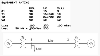
With the system shown in figures, use 100MVA as system base, and 230 kV as base voltage along the transmission line.
1. Based on the system diagram with buses labelled accordingly what should be the rank of the square Y-bus matrix?
2. Build the Y-bus matrix without the Load. What is the element Y11 in susceptance value?
3. Build the Y-bus matrix without the Load. What is the element Y22 in susceptance value?
4. Build the Y-bus matrix without the Load. What is the element Y12 in susceptance value?
5. If you are to convert the real power load to a shunt conductance, what is the value of the conductance in per unit?

Transcribed Image Text:EQUIPMENT RATING
G1
T1
T2
G2
Line
Load
G₁
MVA
90
90
80
90
T₁
38
X (%)
9
10
15/230
230/20 20
18
10
100 ohms
100
230
50 MW+ 150MVar 230
Load
kv
15
Line
2
T₂
38
G₂
Expert Solution
This question has been solved!
Explore an expertly crafted, step-by-step solution for a thorough understanding of key concepts.
This is a popular solution
Trending nowThis is a popular solution!
Step by stepSolved in 5 steps with 4 images

Knowledge Booster
Learn more about
Need a deep-dive on the concept behind this application? Look no further. Learn more about this topic, electrical-engineering and related others by exploring similar questions and additional content below.Similar questions
- In N-R method of Power flow solutions, in case of generator bus, the terms of derivatives with respect to the magnitude of voltages in the Jacobian matrix are zero, due to the constant voltage O True O Falsearrow_forwardExplain the importance of return loss in transmission cabling and its effects on network performance.arrow_forwardA 3-phase, 132 kV, 50 Hz, and 200 km line has a resistance of 0.0765 ohm per km per phase, inductance of 0.605 mH per km per phase, and shunt admittance is 4.79 nF per km per phase. It delivers 40 MVA at 0.8 power factor lagging. Find the voltage regulation and transmission efficiency. Use nominal n circuit. --------arrow_forward
- The reactance diagram in per unit on common base of a simple 3-bus power network is depicted below. Build the ZBus , of this circuit using the direct formulation of building algorithm. Adding the impedance sequence of 1, 2, 3, 4 and 5 when formulating the impedance matrix.arrow_forwardFor the system shown in figure obtain the positive sequence, negative sequence and zero sequence bus impedance matrices. Data are given in table. T₁ 1 2 G₁ to Coto 4+ Item G₁ G₂ Ti T2 Line 1-2 X¹ X² xº 0.10 0.10 0.05 0.10 0.10 0.05 0.25 0.25 0.25 0.25 0.25 0.25 0.30 0.30 0.50 3 T₂ 4 340 G₂arrow_forwardTrue or false 1. The size of Y bus matrix for 6 bus power system is (6)*(5). 2. PV buses constitute the maximum number in a power system. 3. A balanced three phase system consists of positive sequence currents only. 4. Sub transient reactance of generator have a greater value than synchronous reactance and transient reactance for generator 5. Newton Raphson method is high accurate among the other power flow methods.arrow_forward
- In your own word please helparrow_forwardFor different types of buses/nodes in load flow analysis, explain their definitions and possible numbers in a power system.arrow_forwardElectrical Engineering Design a power system network consists of the following: į, 2 generators ii. 2 transformers iii. 2 transmission lines iv. Suitable number of busbars Then, for the designed network, perform the following: j. Load flow analysis. You must clearly identify the bus type to perform this. ii. Fault analysis – Balanced and unbalanced faults Next, perform manual calculations for the following: i, Load flow analysis using either Gauss Seidel or Newton Raphson Method. ii. Fault analysis (balanced and unbalanced faults) on any one fault point.arrow_forward
- Please neglect the simulationarrow_forwardExplain the concept of dynamic line rating (DLR) and its significance in optimizing power transmission capacity.arrow_forwardDiscuss the principles of dynamic line rating (DLR) and its role in maximizing transmission capacity while ensuring reliability.arrow_forward
arrow_back_ios
SEE MORE QUESTIONS
arrow_forward_ios
Recommended textbooks for you
 Introductory Circuit Analysis (13th Edition)Electrical EngineeringISBN:9780133923605Author:Robert L. BoylestadPublisher:PEARSON
 Delmar's Standard Textbook Of ElectricityElectrical EngineeringISBN:9781337900348Author:Stephen L. HermanPublisher:Cengage Learning
 Programmable Logic ControllersElectrical EngineeringISBN:9780073373843Author:Frank D. PetruzellaPublisher:McGraw-Hill Education
 Fundamentals of Electric CircuitsElectrical EngineeringISBN:9780078028229Author:Charles K Alexander, Matthew SadikuPublisher:McGraw-Hill Education
 Electric Circuits. (11th Edition)Electrical EngineeringISBN:9780134746968Author:James W. Nilsson, Susan RiedelPublisher:PEARSON
 Engineering ElectromagneticsElectrical EngineeringISBN:9780078028151Author:Hayt, William H. (william Hart), Jr, BUCK, John A.Publisher:Mcgraw-hill Education,

Introductory Circuit Analysis (13th Edition)
Electrical Engineering
ISBN:9780133923605
Author:Robert L. Boylestad
Publisher:PEARSON

Delmar's Standard Textbook Of Electricity
Electrical Engineering
ISBN:9781337900348
Author:Stephen L. Herman
Publisher:Cengage Learning

Programmable Logic Controllers
Electrical Engineering
ISBN:9780073373843
Author:Frank D. Petruzella
Publisher:McGraw-Hill Education

Fundamentals of Electric Circuits
Electrical Engineering
ISBN:9780078028229
Author:Charles K Alexander, Matthew Sadiku
Publisher:McGraw-Hill Education

Electric Circuits. (11th Edition)
Electrical Engineering
ISBN:9780134746968
Author:James W. Nilsson, Susan Riedel
Publisher:PEARSON

Engineering Electromagnetics
Electrical Engineering
ISBN:9780078028151
Author:Hayt, William H. (william Hart), Jr, BUCK, John A.
Publisher:Mcgraw-hill Education,