
Elements Of Electromagnetics
7th Edition
ISBN: 9780190698614
Author: Sadiku, Matthew N. O.
Publisher: Oxford University Press
expand_more
expand_more
format_list_bulleted
Related questions
Concept explainers
Question
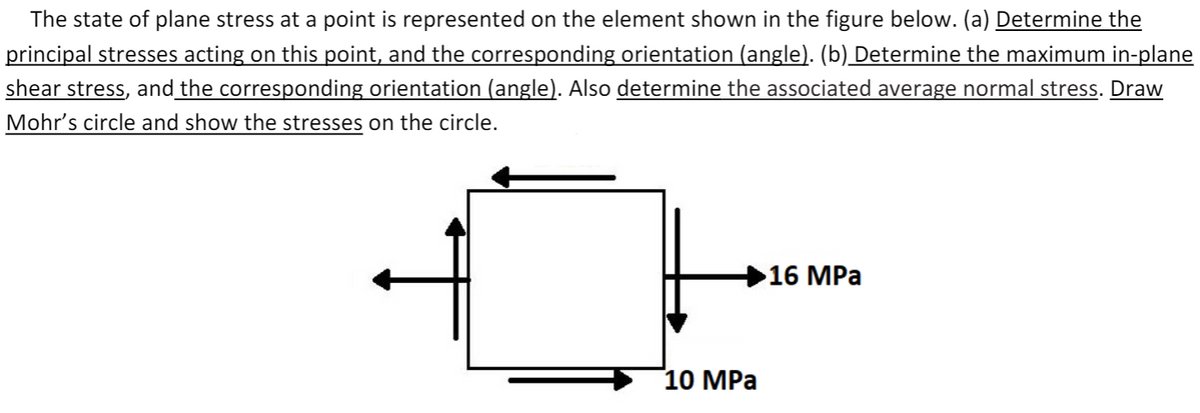

Transcribed Image Text:The state of plane stress at a point is represented on the element shown in the figure below. (a) Determine the
principal stresses acting on this point, and the corresponding orientation (angle). (b) Determine the maximum in-plane
shear stress, and the corresponding orientation (angle). Also determine the associated average normal stress. Draw
Mohr's circle and show the stresses on the circle.
16 MPa
10 MPа
Expert Solution
This question has been solved!
Explore an expertly crafted, step-by-step solution for a thorough understanding of key concepts.

This is a popular solution

Trending nowThis is a popular solution!

Step by stepSolved in 2 steps

Knowledge Booster


Learn more about
Need a deep-dive on the concept behind this application? Look no further. Learn more about this topic, mechanical-engineering and related others by exploring similar questions and additional content below.Similar questions
- fill in the blank please Tensile normal stresses are considered positive in Mohr’s circle. For the specific stress element face, if the shear stress makes the element rotate clockwise, then the normal stress is drawn ( ) the σ axis.arrow_forwardThe diagram below shows Mohr’s circle for a point in a physicalobject that is subjected to plane stress.(a) Determine the stresses σ x, σ y, and τ xy, and show them on astress element.(b) Determine the principal stresses and the maximum in-planeshear stress acting at the point, and show these stresses on anappropriate sketcharrow_forwardA structural member is subjected to the plane stress condition. The state of stress at a point of the member is shown in the figure. 45 MP (1) Draw the Mohr's circle for this 2D state of stress. (2) Determine the principal stresses, the maximum in-plane shear stresses and associated normal stresses acting at this point, (3) Represent these critical stresses on new stress elements, and indicate the angles of rotation of the new stress elements with respect to the original stress elements. 25 MParrow_forward
- In some detail discuss the following: 1) The stresses that would be of concern at the various points shown (A-D) from the external pressure and the applied loads P and F. Don't be afraid to use drawings here! F B y D В Carrow_forwardFind the interal normal stress in all relevant segments of the bar in the picture.arrow_forwardPlease show full work than youarrow_forward
- Suppose that σ = 330 psi and Try = 150 psi in (Figure 1). Figure Part D Specify the orientation of the principal stress. Take the positive direction of rotation counterclockwise. Express your answer in degrees to three significant figures. Op₁= Part E OF 0₂ = ΑΣΦΙΚΗ vec Specify the orientation of the maximum in-plane shear stress. Take the positive direction of rotation counterclockwise. Express your answer in degrees to three significant figures. 0/ —| ΑΣΦ 11 | vec ? ? oarrow_forwardConsider the 2-D state of stress shown below. Using the provided scales graph the Mohr's Circle for the 2-D state of stress with “full" details II-Obtain the Principal Stresses, the Maximum Shear Stress, and complete the table below III- Draw the Planes of Principal and Maximum Shear Stresses in the space provided below Provide "full" details and Use 3 Sig. Fig. in this problem Oy = 15 Ksi Tcw > S y Ox =10 Ksi Тух 5 Ksi 10 5 -20 -15 -10 5 10 15 20 5 10 Tccw > S' O Avg. TMax. 01 02 Op1arrow_forwardThe stresses shown below act on horizontal and vertical planes through a point on the surface of a stressed body. Determine and show on a sketch the principal stresses and the maximum shear stress at this point. 50 MPa -30 MPa 35 MPaarrow_forward
- Use Mohrs circle to find the principle stresses and determine the normal and shear stresses acting on a plane 45 degrees counter clockwise from the Y-plane. Sketch showing the exterior stresses.arrow_forwardIn a volume element with dimensions dx, dy, dz the negatíve y-face has a 2 MPa stress in the positivex-direction, a 3 MPa stress in the negative z-direction, and a 4 MPa stress in the negative y-direction. Which of the following describes the stresses per elasticity convention? Oy = 4 MPa Oyr = -2 MPa Oyz = 3 MPa Oy = -4 MPa Oye = 2 MPa Oyz = -3 MPa Oy = 3 MPa Oye = -4 MPa Oyz = 2 MPa =4 MPa Oyr = 2 MPa Oyz = -3 MPaarrow_forwardA state of plane stress is illustrated in the stress element in Figure 3. (a) (b) 30 MPa Figure 3. 40 MPa 60 MPa y X Find the center, X and Y of the Mohr circle. Plot the Mohr circle using these points. From the Mohr circle, find the principal stress and the maximum shear stress. Indicate on the Mohr circle where these values are found.arrow_forward
arrow_back_ios
SEE MORE QUESTIONS
arrow_forward_ios
Recommended textbooks for you
- Elements Of ElectromagneticsMechanical EngineeringISBN:9780190698614Author:Sadiku, Matthew N. O.Publisher:Oxford University Press
 Mechanics of Materials (10th Edition)Mechanical EngineeringISBN:9780134319650Author:Russell C. HibbelerPublisher:PEARSON
 Thermodynamics: An Engineering ApproachMechanical EngineeringISBN:9781259822674Author:Yunus A. Cengel Dr., Michael A. BolesPublisher:McGraw-Hill Education
  Control Systems EngineeringMechanical EngineeringISBN:9781118170519Author:Norman S. NisePublisher:WILEY
 Mechanics of Materials (MindTap Course List)Mechanical EngineeringISBN:9781337093347Author:Barry J. Goodno, James M. GerePublisher:Cengage Learning
 Engineering Mechanics: StaticsMechanical EngineeringISBN:9781118807330Author:James L. Meriam, L. G. Kraige, J. N. BoltonPublisher:WILEY
Elements Of Electromagnetics
Mechanical Engineering
ISBN:9780190698614
Author:Sadiku, Matthew N. O.
Publisher:Oxford University Press
Mechanics of Materials (10th Edition)
Mechanical Engineering
ISBN:9780134319650
Author:Russell C. Hibbeler
Publisher:PEARSON
Thermodynamics: An Engineering Approach
Mechanical Engineering
ISBN:9781259822674
Author:Yunus A. Cengel Dr., Michael A. Boles
Publisher:McGraw-Hill Education
Control Systems Engineering
Mechanical Engineering
ISBN:9781118170519
Author:Norman S. Nise
Publisher:WILEY
Mechanics of Materials (MindTap Course List)
Mechanical Engineering
ISBN:9781337093347
Author:Barry J. Goodno, James M. Gere
Publisher:Cengage Learning
Engineering Mechanics: Statics
Mechanical Engineering
ISBN:9781118807330
Author:James L. Meriam, L. G. Kraige, J. N. Bolton
Publisher:WILEY