
Elements Of Electromagnetics
7th Edition
ISBN: 9780190698614
Author: Sadiku, Matthew N. O.
Publisher: Oxford University Press
expand_more
expand_more
format_list_bulleted
Related questions
Concept explainers
Question
At a point on the free surface of a machine part (E = 214 GPa, G = 83 GPa), the state of the stress is illustrated in the figure below. For the given plane stress condition determine:
Show the principal stresses and the max in plane shear stress and the average normal stress on an appropriate schematic
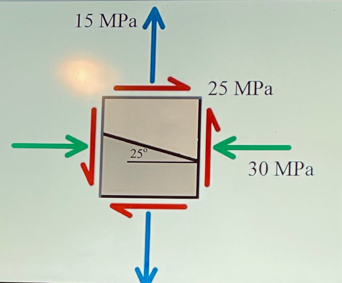

Transcribed Image Text:15 MPa
25 MPa
25°
30 MPa
Expert Solution
This question has been solved!
Explore an expertly crafted, step-by-step solution for a thorough understanding of key concepts.

This is a popular solution

Trending nowThis is a popular solution!

Step by stepSolved in 2 steps

Knowledge Booster


Learn more about
Need a deep-dive on the concept behind this application? Look no further. Learn more about this topic, mechanical-engineering and related others by exploring similar questions and additional content below.Similar questions
- The stresses shown act at a point in a stressed body. Normal and shear stress magnitudes acting on horizontal and vertical planes at the point are S, = 20 MPa, S, = 24 MPa, and Sy = 29 MPa. Assume ß = tan = 21.8°, a = 5, and b = 2. Using the equilibrium equation approach, determine the normal and shear stresses o (positive if tensile, negative if compressive) and z (magnitude only) at this point on the inclined plane shown. Answers: i MPa, T = i MPа.arrow_forwardJust complete the last part of this problem please (part 4). The mohr's circle drawing will help with a complete understanding of these types of problems.arrow_forwardPlease show full work than youarrow_forward
- A rectangular column (blue color) is fixed to a rigid ground (brown color). As shown in the figure, the column is under two external loadings at C. Determine the state of stress at point K of the column and represent the stress components on a stress element.arrow_forward- once answered Correctly will UPVOTE!!arrow_forwardThere’s a force acting in the Y and Z directionarrow_forward
- An element in plane stress is subjected to stresses: 0 = 85 MPa, o, = -30 MPa, and Try = 32MPa, as shown in the figure below. (1) Determine the principal stresses and show them on a sketch of a properly oriented element; (2) Determine the maximum shear stresses and show them on a sketch of a properly oriented element. 30MPA 85MPA 32MPа 1arrow_forwardPlease show all stepsarrow_forwardDetermine the state of stress acting at point D. Take P₁ = 120 kN and P₂ = 45 kN. (Figure 1) Figure L -1.5m- +1.5m-1.5 m- 0.5 m 40 mm 100 mm 60 mm 80 mm 1 of 1 > Find op- Express your answer to three significant figures and include the appropriate units. Enter negative value in the case of compression and positive value in the case of tension. od= - 154.88 Submit Part B Previous Answers Request Answer X Incorrect; Try Again; 3 attempts remaining MPa Find TD- Express your answer to three significant figures and include the appropriate units. JA TD= Value Units ?arrow_forward
- A state of plane stress is illustrated in the stress element in Figure 3. (a) (b) 30 MPa Figure 3. 40 MPa 60 MPa y X Find the center, X and Y of the Mohr circle. Plot the Mohr circle using these points. From the Mohr circle, find the principal stress and the maximum shear stress. Indicate on the Mohr circle where these values are found.arrow_forwardFor a plane stress state, in the original Oxy system we know the component Ox = 120 MPa and Txy = 60 MPa. After the element (see the left figure) is rotated counterclockwise by 45°, we know the stress component Txryı = -60 MPa in the new Ox'y' system (see right figure). Determine the two principal stresses and the absolute maximum shear stress (ra). y Oy Txıy! x' Txy Ox 45 хarrow_forwardThe state of stress acting at a critical point on a wrench is shown in the figure. Determine the smallest yield stress for steel that might be selected for the part, based on the maximum shear stress theory.arrow_forward
arrow_back_ios
SEE MORE QUESTIONS
arrow_forward_ios
Recommended textbooks for you
- Elements Of ElectromagneticsMechanical EngineeringISBN:9780190698614Author:Sadiku, Matthew N. O.Publisher:Oxford University Press
 Mechanics of Materials (10th Edition)Mechanical EngineeringISBN:9780134319650Author:Russell C. HibbelerPublisher:PEARSON
 Thermodynamics: An Engineering ApproachMechanical EngineeringISBN:9781259822674Author:Yunus A. Cengel Dr., Michael A. BolesPublisher:McGraw-Hill Education
  Control Systems EngineeringMechanical EngineeringISBN:9781118170519Author:Norman S. NisePublisher:WILEY
 Mechanics of Materials (MindTap Course List)Mechanical EngineeringISBN:9781337093347Author:Barry J. Goodno, James M. GerePublisher:Cengage Learning
 Engineering Mechanics: StaticsMechanical EngineeringISBN:9781118807330Author:James L. Meriam, L. G. Kraige, J. N. BoltonPublisher:WILEY
Elements Of Electromagnetics
Mechanical Engineering
ISBN:9780190698614
Author:Sadiku, Matthew N. O.
Publisher:Oxford University Press
Mechanics of Materials (10th Edition)
Mechanical Engineering
ISBN:9780134319650
Author:Russell C. Hibbeler
Publisher:PEARSON
Thermodynamics: An Engineering Approach
Mechanical Engineering
ISBN:9781259822674
Author:Yunus A. Cengel Dr., Michael A. Boles
Publisher:McGraw-Hill Education
Control Systems Engineering
Mechanical Engineering
ISBN:9781118170519
Author:Norman S. Nise
Publisher:WILEY
Mechanics of Materials (MindTap Course List)
Mechanical Engineering
ISBN:9781337093347
Author:Barry J. Goodno, James M. Gere
Publisher:Cengage Learning
Engineering Mechanics: Statics
Mechanical Engineering
ISBN:9781118807330
Author:James L. Meriam, L. G. Kraige, J. N. Bolton
Publisher:WILEY