Elements Of Electromagnetics
7th Edition
ISBN: 9780190698614
Author: Sadiku, Matthew N. O.
Publisher: Oxford University Press
expand_more
expand_more
format_list_bulleted
Concept explainers
Question

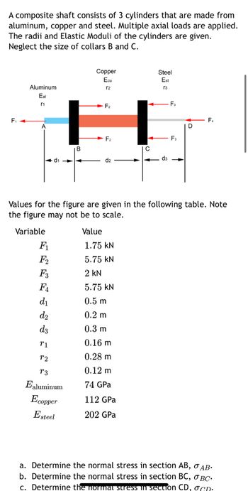
Transcribed Image Text:A composite shaft consists of 3 cylinders that are made from
aluminum, copper and steel. Multiple axial loads are applied.
The radii and Elastic Moduli of the cylinders are given.
Neglect the size of collars B and C.
F₁
Aluminum
Eal
r1
F₁
F₂
F3
FA
d₁
d₂
d3
F₂
H
F₂
B
d₁
Copper
Ecu
r2
T1
72
T3
Ealuminum
Ecopper
Esteel
Value
C
1.75 KN
5.75 KN
2 KN
5.75 KN
0.5 m
0.2 m
0.3 m
0.16 m
0.28 m
0.12 m
74 GPa
112 GPa
202 GPa
Steel
Est
[3
d3
Values for the figure are given in the following table. Note
the figure may not be to scale.
Variable
F₂
F₂
D
F₁
a. Determine the normal stress in section AB, OAB.
b. Determine the normal stress in section BC, OBC.
c. Determine the normal stress in section CD, gcn.

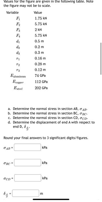
Transcribed Image Text:Values for the figure are given in the following table. Note
the figure may not be to scale.
Variable
O AB=
OBC=
8
F₁
F2
F3
FA
d₁
d₂
72
73
Ealuminum
Ecopper
Esteel
OCD=
d3
=
T1
a. Determine the normal stress in section AB, OAB.
b. Determine the normal stress in section BC, OBC.
c. Determine the normal stress in section CD, OCD.
Determine the displacement of end A with respect to
end D, 8₁.
d.
D
Round your final answers to 3 significant digits/figures.
Value
1.75 KN
5.75 KN
2 KN
5.75 kN
0.5 m
0.2 m
0.3 m
0.16 m
0.28 m
0.12 m
74 GPa
112 GPa
202 GPa
kPa
kPa
kPa
m
Expert Solution
This question has been solved!
Explore an expertly crafted, step-by-step solution for a thorough understanding of key concepts.
Step by stepSolved in 3 steps with 35 images

Knowledge Booster
Learn more about
Need a deep-dive on the concept behind this application? Look no further. Learn more about this topic, mechanical-engineering and related others by exploring similar questions and additional content below.Similar questions
- Find the tension in the cables and reaction force at point O.arrow_forwardQUESTION 1 Determine the reaction moment at x = 0 in kN-m. QUESTION 2 Determine the vertical reaction force at x = 0 in kN. QUESTION 3 (1-3) Determine the horizontal reaction force at x = 0 in kN. The distributed load, f(x), is equal to 100 kN/m. /// f(x) 3 marrow_forwardA metal bar is made out of A-36 steel and has a diameter d = 23mm with the end at A fixed to the wall. There is are balanced axial loads at B of P₁ = 30 kN and a point load at C 35 kN. The distance from A to B is L₁ of P2 570 mm 390 mm. Calculate the = and the distance from B to C is L2 displacement of point C relative to point A. A L₁ ↑ d B L2 - P₁₁ Р1 С The displacement at C is 8 = -0.00306 d - cc 080 BY NO SA 2021 Cathy Zupke P₂ x mmarrow_forward
- Note: J3 = J2 46 mm G3 = G2 4.93×10° mm (1) 16 kN-m 50 GPa (2) C2 = 34 mm (3) J2 2.10x10° mm* B 900 mm 35 GPa 900 mm A composite torsion member consists of a tubular shell (1) bonded to length AB of a continuous solid T1 kN-m shaft that extends from A to C, which is labeled T2 kN-m (2) and (3). A concentrated torque T is applied to MPa free end C of the shaft in the direction shown. MPa Determine the internal torques and shear stresses PC rad in shell (1) and core (2) (i.e., between A and B). 1st 2nd 3rd Enter Also, determine the rotation angle at end C. attempt II || || I| || || Shaft propertiesarrow_forwardI need help on solving this questionarrow_forwardHandwritten solution+FBD and explanation.arrow_forward
- A solid aluminum shaft of 100 mm diameter fits concentrically in a hollow steel tube. Determine the minimum internal diameter in mm of the steel tube so that no contact pressure exist when the aluminum shaft carries an axial compressive load of 503 KN. Assume Poisson's ratio = 1/3 and a modulus of elasticity of the aluminum rod is 75 GPa. Use 4 decimal places. Add your answerarrow_forwardThe two pipes are made of the steel (E=210GPa, sy=420MPa)material and are connected as shown in Figure 3 and loaded by a force P at point C. The cross-sectional area of AC and CB are 600 mm2 and 900 mm2, respectively. The length of AC and CB are same a=b= (see attached file) If AC becomes plastic, determine the displacement of the step, the ultimate load of the stepped bar, draw a load-deflection diagram for the sectional area of AC and CB. a=b=9marrow_forwardFind H1,R1 and R2arrow_forward
- A steel [E = 25500 ksi] pipe column (1) with a cross-sectional area of A1 = 5.60 in.2 is connected at flange 8 to an aluminum alloy [E = 17500 ksi] pipe (2) with a cross-sectional area of A2 = 4.40 in.2. The assembly is connected to rigid supports at A and C. For the loading shown, determine the normal force in the steel pipe (1). A (1) 120 in. B 30 kips 30 kips 144 in. Carrow_forwardThe two angle bars are used to support a tensile load "T". Assume the tensile load to be equally resisted by each angle. 400 mm x 20 mm THK Gusset Plate The steel used is L 6 x 6 x 1. Properties: A = 7096.76 mm? y = 47.244 mm Fy = 248 MPa Fu = 400 MPa b = 152.4 mm b. t = 25.4 mm x = 47.244 mm Effective hole diameter = 25 mm y Use case 2 for shear lag factor. Use NSCP 2015 code. 1. Determine the maximum allowable load that can be carried by the two L6 x 6 x1 based on yielding of the gross section--- 2. Determine the maximum factored load that can be carried by two L6 x 6 x 1, based on the fracture of the effective net area.---- 3. Determine the maximum allowable tensile load that can be carried.------ 4. Determine the maximum factored tensile load that can be carried-- boarrow_forward55arrow_forward
arrow_back_ios
SEE MORE QUESTIONS
arrow_forward_ios
Recommended textbooks for you
 Elements Of ElectromagneticsMechanical EngineeringISBN:9780190698614Author:Sadiku, Matthew N. O.Publisher:Oxford University Press
 Mechanics of Materials (10th Edition)Mechanical EngineeringISBN:9780134319650Author:Russell C. HibbelerPublisher:PEARSON
 Thermodynamics: An Engineering ApproachMechanical EngineeringISBN:9781259822674Author:Yunus A. Cengel Dr., Michael A. BolesPublisher:McGraw-Hill Education
 Control Systems EngineeringMechanical EngineeringISBN:9781118170519Author:Norman S. NisePublisher:WILEY
 Mechanics of Materials (MindTap Course List)Mechanical EngineeringISBN:9781337093347Author:Barry J. Goodno, James M. GerePublisher:Cengage Learning
 Engineering Mechanics: StaticsMechanical EngineeringISBN:9781118807330Author:James L. Meriam, L. G. Kraige, J. N. BoltonPublisher:WILEY

Elements Of Electromagnetics
Mechanical Engineering
ISBN:9780190698614
Author:Sadiku, Matthew N. O.
Publisher:Oxford University Press

Mechanics of Materials (10th Edition)
Mechanical Engineering
ISBN:9780134319650
Author:Russell C. Hibbeler
Publisher:PEARSON

Thermodynamics: An Engineering Approach
Mechanical Engineering
ISBN:9781259822674
Author:Yunus A. Cengel Dr., Michael A. Boles
Publisher:McGraw-Hill Education

Control Systems Engineering
Mechanical Engineering
ISBN:9781118170519
Author:Norman S. Nise
Publisher:WILEY

Mechanics of Materials (MindTap Course List)
Mechanical Engineering
ISBN:9781337093347
Author:Barry J. Goodno, James M. Gere
Publisher:Cengage Learning

Engineering Mechanics: Statics
Mechanical Engineering
ISBN:9781118807330
Author:James L. Meriam, L. G. Kraige, J. N. Bolton
Publisher:WILEY