
Elements Of Electromagnetics
7th Edition
ISBN: 9780190698614
Author: Sadiku, Matthew N. O.
Publisher: Oxford University Press
expand_more
expand_more
format_list_bulleted
Related questions
Question
Got this wrong. please help and show work then round the final answer to 3 sig figs.
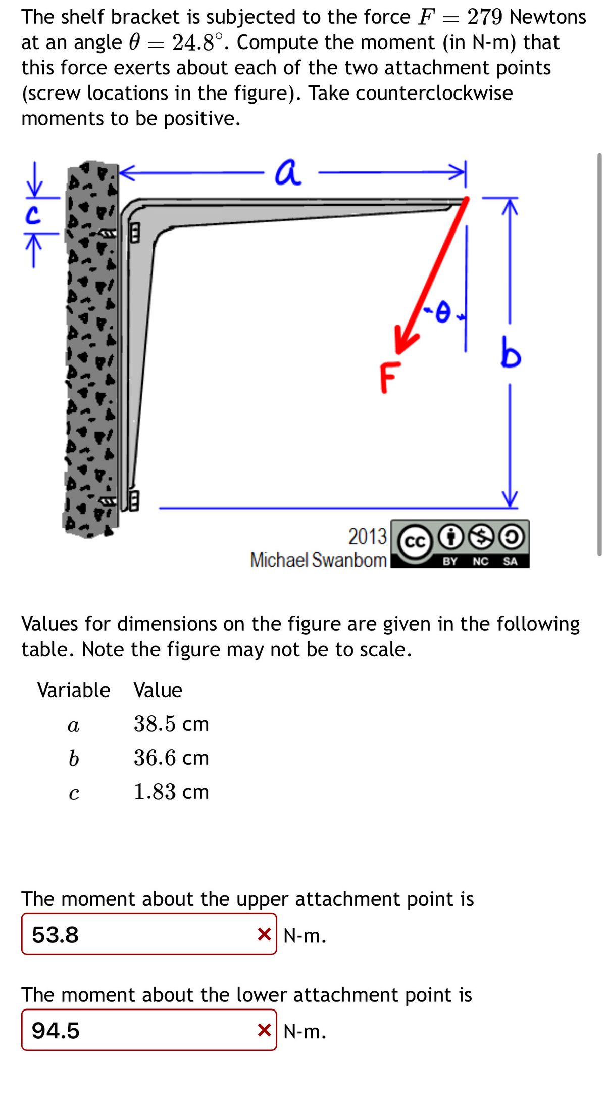

Transcribed Image Text:The shelf bracket is subjected to the force F = 279 Newtons
at an angle = 24.8°. Compute the moment (in N-m) that
this force exerts about each of the two attachment points
(screw locations in the figure). Take counterclockwise
moments to be positive.
a
→luk
b
F
2013 cc
CC
Michael Swanbom
BY NC SA
Values for dimensions on the figure are given in the following
table. Note the figure may not be to scale.
Variable Value
a
38.5 cm
b
36.6 cm
с
1.83 cm
The moment about the upper attachment point is
53.8
☑ N-m.
The moment about the lower attachment point is
94.5
× N-m.
Expert Solution
This question has been solved!
Explore an expertly crafted, step-by-step solution for a thorough understanding of key concepts.

Step by stepSolved in 2 steps with 1 images

Knowledge Booster

Similar questions
- The shelf bracket is subjected to the force F = 372 Newtons at an angle = 21.4°. Compute the moment (in N-m) that this force exerts about each of the two attachment points (screw locations in the figure). Take counterclockwise moments to be positive. a duk F -0 2013 cc Michael Swanbom BY NC O SA Values for dimensions on the figure are given in the following table. Note the figure may not be to scale. Variable Value a 43.0 cm b 32.3 cm с 2.58 cm The moment about the upper attachment point is N-m. The moment about the lower attachment point is N-m.arrow_forwardTwo couple forces F = 67N, F - 61N, act on the frame and given that d- 4m and 0- 28". The other length parameters are a = 4m, b- 8m, C- 12m, and e- 12m. Compute the moment by the following methods: -F, -F1 F1 a) Find the moment of each couple by using cross product and add them up. M: kị N m b) Sum up the moments of all forces component about point B resolve forces into a and y components N- marrow_forwardS00 Ib In the fig. shown, compute the ff: (16-18) the resultant using cosine law (force polygon) 60 R = 35 (19-20) the angle of the R measured 500 lb cW from the x- axis.arrow_forward
- The shelf bracket is subjected to the force F= 234 Newtons at an angle = 24.2°. Compute the moment (in N-m) that this force exerts about each of the two attachment points (screw locations in the figure). Take counterclockwise moments to be positive. a uk a b с 18.0 cm 13.5 cm 1.35 cm F 2013 cc Michael Swanbom Values for dimensions on the figure are given in the following table. Note the figure may not be to scale. Variable Value The moment about the upper attachment point is -0. The moment about the lower attachment point is BY NC SA N-m. N-m.arrow_forward6 in 60° 20 in Statics Instructor A vertical force of P = 100 lb is required to remove the nail at C from the board. Determine the magnitude of the moment about B exerted by the 100 lb vertical force. Draw a free body diagram for the system. Then, use what you know about moments to solve for Mp What is the magnitude of the moment at point B due to P if P = 100 lb and 9 = 10"? Round to the nearest whole number. Enter a response then click Submit below lb inarrow_forwardFill the table with the correct data and signs (+) (-) please.arrow_forward
- Need help, round answers to 3 sig figs pleasearrow_forwardA vehicle launch wall structure is being assembled, as seen in the figure. The rocket that needs this wall will be discussed in your next class. During assembly if the launchpad, the walls must be individually supported - here this is done by a specialized cable set to hold things into place, connected to the wall at B'and temporary connections placed at E and G for stability. The wall itself is made of a heavy composite material (learn more about launch structures with the read button below). The tension in the cable BG is 996 Newtons. The wall itself is X = 4 m by Y = 2 m. X m E Y m 1m G 3 marrow_forwardAccording To F1=600N,F2=800N and F3=400N for the forces acting on the drawbar in the figure; Find the angle 0 required for the vertical component of the resultant force to be 432N and calculate the directional cosines of the resultantarrow_forward
- Help Save & Exit Check Required information A rope connecting points A and B supports the force Fshown in the figure. Write expressions using Cartesian vector representation for the following. Take L= 8 ft and F= 12 lb. NOTE: This is a multi-part question. Once an answer is submitted, you will be unable to return to this part. B 30° F T AB : the position vector from A to B. TAB of 17 Next > < Prev 6. 9. 41arrow_forwardНОМE WORK 3 Determine the resultant force at A. for the figure below Hint : 1- Find the position of all points A,B.C (x, y., z) 2. Find Fas und FAC 3. Find Tanl and Iracl 4. Find FAg = F UA and Fac = F UAC 5- Finally find R and a, B.y 3m Fc= 500N FB= 500N 3m 5m 3m B 2m 4m 5marrow_forwardRequired information A rope connecting points A and B supports the force F shown in the figure. Write expressions using Cartesian vector representation for the following. Take L = 8 ft and F= 12 lb. NOTE: This is a multi-part question. Once an answer is submitted, you will be unable to return to this part. y 30° es ÜAB : the unit vector in the direction from A to B. ûAB =arrow_forward
arrow_back_ios
SEE MORE QUESTIONS
arrow_forward_ios
Recommended textbooks for you
- Elements Of ElectromagneticsMechanical EngineeringISBN:9780190698614Author:Sadiku, Matthew N. O.Publisher:Oxford University Press
 Mechanics of Materials (10th Edition)Mechanical EngineeringISBN:9780134319650Author:Russell C. HibbelerPublisher:PEARSON
 Thermodynamics: An Engineering ApproachMechanical EngineeringISBN:9781259822674Author:Yunus A. Cengel Dr., Michael A. BolesPublisher:McGraw-Hill Education
  Control Systems EngineeringMechanical EngineeringISBN:9781118170519Author:Norman S. NisePublisher:WILEY
 Mechanics of Materials (MindTap Course List)Mechanical EngineeringISBN:9781337093347Author:Barry J. Goodno, James M. GerePublisher:Cengage Learning
 Engineering Mechanics: StaticsMechanical EngineeringISBN:9781118807330Author:James L. Meriam, L. G. Kraige, J. N. BoltonPublisher:WILEY
Elements Of Electromagnetics
Mechanical Engineering
ISBN:9780190698614
Author:Sadiku, Matthew N. O.
Publisher:Oxford University Press
Mechanics of Materials (10th Edition)
Mechanical Engineering
ISBN:9780134319650
Author:Russell C. Hibbeler
Publisher:PEARSON
Thermodynamics: An Engineering Approach
Mechanical Engineering
ISBN:9781259822674
Author:Yunus A. Cengel Dr., Michael A. Boles
Publisher:McGraw-Hill Education
Control Systems Engineering
Mechanical Engineering
ISBN:9781118170519
Author:Norman S. Nise
Publisher:WILEY
Mechanics of Materials (MindTap Course List)
Mechanical Engineering
ISBN:9781337093347
Author:Barry J. Goodno, James M. Gere
Publisher:Cengage Learning
Engineering Mechanics: Statics
Mechanical Engineering
ISBN:9781118807330
Author:James L. Meriam, L. G. Kraige, J. N. Bolton
Publisher:WILEY