Mechanics of Materials (MindTap Course List)
9th Edition
ISBN: 9781337093347
Author: Barry J. Goodno, James M. Gere
Publisher: Cengage Learning
expand_more
expand_more
format_list_bulleted
Question

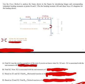
Transcribed Image Text:Use the Force Method to analyse the frame shown in the Figure by introducing hinges and corresponding
redundant bending moments at points B and C. Plot the bending moment (M) and shear force (V) diagrams for
the loading shown.
12 kN/m
A
16 kN↓
B
C
4.5 m
4.5 m
6 m
El is constant all across the structure.
72 kN.m
D
D'℃
Assume the unit moments this
way to get consistent results
4.5 m
4.5 m
A) Find X1 (see the similar example(s) of the note if you do not know what X1, X2 are) - X1 is associated with the
unit moment at B.
B) Find X2. Note: X2 is associated with the unit moment at C.
C) Based on X1 and X2: Find RAX (Horizontal reaction at A)|
D) Based on Xland X2: Find RAY (Vertical reaction at A)
1
Expert Solution
This question has been solved!
Explore an expertly crafted, step-by-step solution for a thorough understanding of key concepts.
Step by stepSolved in 2 steps with 1 images

Knowledge Booster
Similar questions
- Don't use Artificial intelligencearrow_forwardBridges are usually modeled as simply supported beams. Your role in a building and construction company is to analyse and design the bridge based on simply supported beam theory. Your manager asked you to perform a stress analysis for bridge element modelled as simply supported beam shown in the Figure.1(a), this task is best achieved by performing the following required steps: 2 kN 3 kN/m 3 kN/m 3kN.m A 0.5 kN 4.5 kN kN 2 m 1 т+1m- 2 m R| -2 m (а) (b) Figure.1: (a) Bridge element modelled as simply supported beam (b) Beam sectionarrow_forwardUse singularity functions to obtain shear force, bending moment, and deflections of the beams for the following 2 casesarrow_forward
- Please only include the sketch mentioned in the question as I have already provided the calculation and answers to the question.arrow_forwardSOLVE STEP BY STEP WITHOUT ARTIFICIAL INTELLIGENCE, SOLVE BY HAND STEP BY STEP Virtual load method on frames. For each case, consider El = constant: 2. Calculate the horizontal, vertical and angular displacement at node B. Draw the axial force, shear force and bending moment diagrams. 1 Ton/m 1 Ton B A DIMENSIONS IN m 5.00 3.00arrow_forwardusing MATLABarrow_forward
- Can you help me find the moment reactions aswell as Shear force and bending moments. With a UDLarrow_forwardA 16 kN/m 80 kN.m C 75 kN B 2 m 2m 1 m 2 m 5 m El is constant all across the structure. D Use the Force Method to analyse the beam shown in the Figure by introducing hinges and corresponding redundant bending moments at points A, B, C. Plot the bending moment (M) and shear force (V) diagrams for the loading shown. A) Find X1 (see the similar example(s) of the note if you do not know what X1, X2 and X3 are) - XI is associated with the unit moment at A. B) Find X2. Note: X2 is associated with the unit moment at B. C) Find X3. Note: X3 is associated with the unit moment at C. D) Based on X1, X2, and X3: Find Ray (Vertical reaction at A). E) Based on X1, X2, and X3: Find Roy (Vertical reaction at D)arrow_forwardA folding tray mechanism is attached to a wall as shown. Find the internal forces and bending moment in the lower support arm at section s-s, located midway between points B and E, when a force of F = 250 N is applied at an angle of 0 = 32°. A B. 's E D k a- b – Values for dimensions on the figure are given in the following table. Note the figure may not be to scale. Variable Value a 17 cm b 26 cm 35 cm hi 25 cm h2 18 cm The internal axial load at section s-s is A = N. The internal shear load at section s-s is V = N. The internal bending moment at section s-s is M = N-m.arrow_forward
- find second moment of area for cases 4-7arrow_forwardNeeds Complete typed solution with 100 % accuracy.arrow_forwardRAX Ray 0.2m 100Nm 100N 1000 0.3m A. Draw Shear force diagram B. Draw Bending moment diagram C. Draw Torque diagram D. Draw Axial force diagram ZOON 1000m 2000 0.2m y RBy Ł 10,000 N 10,000 Narrow_forward
arrow_back_ios
SEE MORE QUESTIONS
arrow_forward_ios
Recommended textbooks for you
 Mechanics of Materials (MindTap Course List)Mechanical EngineeringISBN:9781337093347Author:Barry J. Goodno, James M. GerePublisher:Cengage Learning

Mechanics of Materials (MindTap Course List)
Mechanical Engineering
ISBN:9781337093347
Author:Barry J. Goodno, James M. Gere
Publisher:Cengage Learning