
Introductory Circuit Analysis (13th Edition)
13th Edition
ISBN: 9780133923605
Author: Robert L. Boylestad
Publisher: PEARSON
expand_more
expand_more
format_list_bulleted
Related questions
Concept explainers
Question
Solve i) and ii) and show all the steps in detail with the sketch

Transcribed Image Text:A ..
Bo
Device 1
-Ds
·D6
·D7
XOR
Io
I,
0₁
0₂ www
www
03
04
Device 2
BA
BB
Be
BD
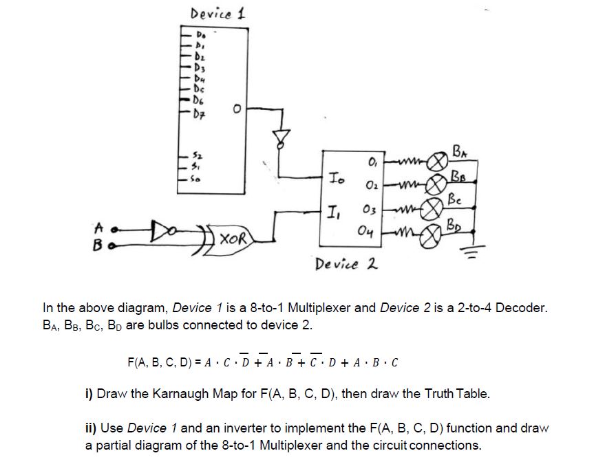
In the above diagram, Device 1 is a 8-to-1 Multiplexer and Device 2 is a 2-to-4 Decoder.
BA, BB, BC, BD are bulbs connected to device 2.
F(A, B, C, D) = A CD+A·B + C D + A.B.C
I
i) Draw the Karnaugh Map for F(A, B, C, D), then draw the Truth Table.
ii) Use Device 1 and an inverter to implement the F(A, B, C, D) function and draw
a partial diagram of the 8-to-1 Multiplexer and the circuit connections.
Expert Solution
This question has been solved!
Explore an expertly crafted, step-by-step solution for a thorough understanding of key concepts.

Step by stepSolved in 6 steps with 3 images

Knowledge Booster


Learn more about
Need a deep-dive on the concept behind this application? Look no further. Learn more about this topic, electrical-engineering and related others by exploring similar questions and additional content below.Similar questions
- please answer both questions with most detail as possible. if you use a formulas and manipulate it, please specify from where you got it from. THANK YOUarrow_forwardAfter solving for the total resistance, and the applied voltage being a given for the circuit, the next logical step is to .....? so that individual component voltages and currents can be found.arrow_forwardFull detailed answer pleasearrow_forward
- 4. Consider the following circuit. 3R SR 2R a) How many distinct currents flow in this circuit? The four loops shown are labeled A - D, and the junctions are labeled a - d. b) If we had to solve for these currents, how many independent equations would we need? c) Which loops and/or junctions would you choose, if you had to solve for the currents? (Many answers are possible here.) This diagram shows several different loops and junctions in the circuit. d) Set up a system of equations that would allow you to solve for the currents.arrow_forwardHello Sir.Good Night. I have a question in my home work related Control System Lesson. The following below is my question.Please advise, Thank you so much.arrow_forwardquestion is belowarrow_forward
- In a series circuit, certain general rules may be stated with regard to quantities of voltage, current, resistance, and power. Express these rules, using your own words: "In a series circuit, voltage..." "In a series circuit, current..." "In a series circuit, resistance..." "In a series circuit, power..." For each of these rules, explain why it is true.arrow_forwardResistor and RC Circuits Problem 12: Consider the circuit in the figure, with the current directions defined as shown. There are four resistors in this circuit (R1, R2, R3, and R4) and four batteries with emfs ℰ1 = 15.5 V, ℰ2 = 3.5 V, ℰ3 = 14 V, and ℰ4 = 27.3 V, each with internal resistance given by ri as marked in the figure. Part (a) Calculate the current I1 in amps. Part (b) Calculate the current I2 in amps. Part (c) Calculate the current I3 in amps.arrow_forwardI need an expert solution in MATLAB language for the question, and I need the solution to be using MATLAB and in the form of an image. I do not need any notes with the program, just an explanation at the end of the image. By the way, two questions. Q2. Write a MATLAB user-defined function, freefall(), that computes the velocity and the distance of a free fall object. The velocity and the distance of a free fall object can be written as: v = gt y = yo+gt² where yo is the initial position, t is the time travelled and g is the acceleration due to gravity (- 9.81 m/s2). Note that the initial position can only be a scalar value. Q7. Write a user-defined MATLAB Function for the following math function: ((xy-5)² z = if x, y > 0 elsewhere The inputs to the function are x and y, where the output is z. Write the function such that x and y can be vectors. I. II. Use the function to calculate z(3,4) and z(5, -7). Use the function to make a colored 3D plot of the function z for -5arrow_forward
- "To solve a circuit" means to use the values of potentials and resistances to find all currents passing through, and voltage drops across all elements in the circuit. Create a general procedure to solve any circuit DC circuit with any number of resistors. You may use the Structure Physics Problem-Solving Method as a model.arrow_forwardcan someone show me how to do this problem and explain the answer step by steparrow_forwardTwo coils are placed close to each other as shown in the figure. The coil on the left is connected to a battery and a switch, and the coil on the right is connected to a resistor.What is the direction of the current in the resistori. an instant after closing the switch?ii. after the switch has been closed for several seconds?iii. an instant after opening the switch?Choose your answers betweento. on the leftb. on the rightc. the current is zero.And clearly explain the reason for your answer.arrow_forward
arrow_back_ios
arrow_forward_ios
Recommended textbooks for you
- Introductory Circuit Analysis (13th Edition)Electrical EngineeringISBN:9780133923605Author:Robert L. BoylestadPublisher:PEARSON
 Delmar's Standard Textbook Of ElectricityElectrical EngineeringISBN:9781337900348Author:Stephen L. HermanPublisher:Cengage Learning
 Programmable Logic ControllersElectrical EngineeringISBN:9780073373843Author:Frank D. PetruzellaPublisher:McGraw-Hill Education
  Fundamentals of Electric CircuitsElectrical EngineeringISBN:9780078028229Author:Charles K Alexander, Matthew SadikuPublisher:McGraw-Hill Education
 Electric Circuits. (11th Edition)Electrical EngineeringISBN:9780134746968Author:James W. Nilsson, Susan RiedelPublisher:PEARSON
 Engineering ElectromagneticsElectrical EngineeringISBN:9780078028151Author:Hayt, William H. (william Hart), Jr, BUCK, John A.Publisher:Mcgraw-hill Education,
Introductory Circuit Analysis (13th Edition)
Electrical Engineering
ISBN:9780133923605
Author:Robert L. Boylestad
Publisher:PEARSON
Delmar's Standard Textbook Of Electricity
Electrical Engineering
ISBN:9781337900348
Author:Stephen L. Herman
Publisher:Cengage Learning
Programmable Logic Controllers
Electrical Engineering
ISBN:9780073373843
Author:Frank D. Petruzella
Publisher:McGraw-Hill Education
Fundamentals of Electric Circuits
Electrical Engineering
ISBN:9780078028229
Author:Charles K Alexander, Matthew Sadiku
Publisher:McGraw-Hill Education
Electric Circuits. (11th Edition)
Electrical Engineering
ISBN:9780134746968
Author:James W. Nilsson, Susan Riedel
Publisher:PEARSON
Engineering Electromagnetics
Electrical Engineering
ISBN:9780078028151
Author:Hayt, William H. (william Hart), Jr, BUCK, John A.
Publisher:Mcgraw-hill Education,