
Introductory Circuit Analysis (13th Edition)
13th Edition
ISBN: 9780133923605
Author: Robert L. Boylestad
Publisher: PEARSON
expand_more
expand_more
format_list_bulleted
Related questions
Concept explainers
Question
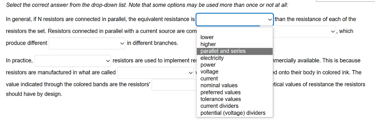

Transcribed Image Text:Select the correct answer from the drop-down list. Note that some options may be used more than once or not at all:
In general, if N resistors are connected in parallel, the equivalent resistance is
resistors the set. Resistors connected in parallel with a current source are com
produce different
✓in different branches.
In practice,
resistors are manufactured in what are called
✓ resistors are used to implement res
value indicated through the colored bands are the resistors'
should have by design.
lower
higher
parallel and series
electricity
power
✓voltage
current
nominal values
preferred values
tolerance values
current dividers
potential (voltage) dividers
✓than the resistance of each of the
which
mercially available. This is because
ed onto their body in colored ink. The
etical values of resistance the resistors

Transcribed Image Text:Select the correct answer from the drop-down list. Note that some options may be used more than once or not at all:
In general, if N resistors are connected in parallel, the equivalent resistance is
resistors the set. Resistors connected in parallel with a current source are commonly used to implement
produce different
✓in different branches.
In practice,
resistors are manufactured in what are called
value indicated through the colored bands are the resistors'
should have by design.
than the resistance of each of the
✓, which
resistors are used to implement resistors whose value are not commercially available. This is because
✓ with their resistance value printed onto their body in colored ink. The
✓, that is, the theoretical values of resistance the resistors
Expert Solution
This question has been solved!
Explore an expertly crafted, step-by-step solution for a thorough understanding of key concepts.

Step by stepSolved in 3 steps

Knowledge Booster


Learn more about
Need a deep-dive on the concept behind this application? Look no further. Learn more about this topic, electrical-engineering and related others by exploring similar questions and additional content below.Similar questions
- Need help with parts D and E please.arrow_forwardShow me a circuit diagram that has a 10V voltage source called, E1, which supplies a current I1. There are two resistors in series: R1 which is 4.8ohms and R2 which is 3.2ohms. There is a node between the resistors called “a”. The ground is on the negative end of the voltage source.arrow_forwardFive resistors are connected as shown in the figure. What is the equivalent resistance of this combination between points a and b? RI R: ww ww Ra www R Rs www www where R1 = 50 R2 = 72 R3 = 82 R4 = 42 R5 = 6 2arrow_forward
- help with part c and d. not allowed to redraw circuitarrow_forwardParallel Circuits Review In a Parallel circuit, the Voltage across each cell is the same, while the total current is equal to sum of the currents in each resistor. In a series circuits, the total voltage is equal the sum of the voltages across each resistor. The current, however is the same for each resistor, 1. The circuit shown in the diagram consists of two resistors connected in parallel to a cell. The value of Itotal is equal to 30 A. What is the value of V(2)? 50 -ww www 2. The circuit shown in the diagram consists of two resistors connected in parallel to a cell. The value of the current given by the second ammeter, / is 3 A. What is the value of I (total)? 3. A student sets up the circuit shown in the diagram. The value of Itotal is 8 A and the value of I is 6 A. w www a). What is the value of /(2)? b). What is the potential difference supplied by the cell the circuit?arrow_forwardNeed the correct answer with solution as soon as possible. I will give an upvote if you does. Thank you.arrow_forward
- 1. Type of circuit? 2. What is the total resistance? 3. What is current flow through R1 and R2 ? 4. What is voltage across R1 and R2 ?arrow_forwardcan someone explain to me the logic how to do this problem step by step I have the answers but I want to know how to do each part and understand the concepts of what is happeningarrow_forwardA circuit has one 10 Ohm resistor and you want to drop the current by a factor of two. Which of the methods below would allow this? You could add: (Choose any that apply. ) two 5 Ohm resistors another 10 Ohm resistor ten 1 Ohm resistors one 20 Ohm resistorarrow_forward
arrow_back_ios
arrow_forward_ios
Recommended textbooks for you
- Introductory Circuit Analysis (13th Edition)Electrical EngineeringISBN:9780133923605Author:Robert L. BoylestadPublisher:PEARSON
 Delmar's Standard Textbook Of ElectricityElectrical EngineeringISBN:9781337900348Author:Stephen L. HermanPublisher:Cengage Learning
 Programmable Logic ControllersElectrical EngineeringISBN:9780073373843Author:Frank D. PetruzellaPublisher:McGraw-Hill Education
  Fundamentals of Electric CircuitsElectrical EngineeringISBN:9780078028229Author:Charles K Alexander, Matthew SadikuPublisher:McGraw-Hill Education
 Electric Circuits. (11th Edition)Electrical EngineeringISBN:9780134746968Author:James W. Nilsson, Susan RiedelPublisher:PEARSON
 Engineering ElectromagneticsElectrical EngineeringISBN:9780078028151Author:Hayt, William H. (william Hart), Jr, BUCK, John A.Publisher:Mcgraw-hill Education,
Introductory Circuit Analysis (13th Edition)
Electrical Engineering
ISBN:9780133923605
Author:Robert L. Boylestad
Publisher:PEARSON
Delmar's Standard Textbook Of Electricity
Electrical Engineering
ISBN:9781337900348
Author:Stephen L. Herman
Publisher:Cengage Learning
Programmable Logic Controllers
Electrical Engineering
ISBN:9780073373843
Author:Frank D. Petruzella
Publisher:McGraw-Hill Education
Fundamentals of Electric Circuits
Electrical Engineering
ISBN:9780078028229
Author:Charles K Alexander, Matthew Sadiku
Publisher:McGraw-Hill Education
Electric Circuits. (11th Edition)
Electrical Engineering
ISBN:9780134746968
Author:James W. Nilsson, Susan Riedel
Publisher:PEARSON
Engineering Electromagnetics
Electrical Engineering
ISBN:9780078028151
Author:Hayt, William H. (william Hart), Jr, BUCK, John A.
Publisher:Mcgraw-hill Education,