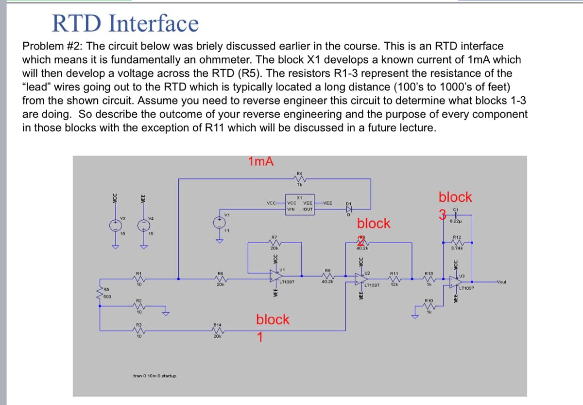
RTD Interface Problem #2: The circuit below was briely discussed earlier in the course. This is an RTD interface which means it is fundamentally an ohmmeter. The block X1 develops a known current of 1mA which will then develop a voltage across the RTD (R5). The resistors R1-3 represent the resistance of the "lead" wires going out to the RTD which is typically located a long distance (100's to 1000's of feet) from the shown circuit. Assume you need to reverse engineer this circuit to determine what blocks 1-3 are doing. So describe the outcome of your reverse engineering and the purpose of every component in those blocks with the exception of R11 which will be discussed in a future lecture.
RTD Interface Problem #2: The circuit below was briely discussed earlier in the course. This is an RTD interface which means it is fundamentally an ohmmeter. The block X1 develops a known current of 1mA which will then develop a voltage across the RTD (R5). The resistors R1-3 represent the resistance of the "lead" wires going out to the RTD which is typically located a long distance (100's to 1000's of feet) from the shown circuit. Assume you need to reverse engineer this circuit to determine what blocks 1-3 are doing. So describe the outcome of your reverse engineering and the purpose of every component in those blocks with the exception of R11 which will be discussed in a future lecture.

Delmar's Standard Textbook Of Electricity
7th Edition
ISBN:9781337900348
Author:Stephen L. Herman
Publisher:Stephen L. Herman
Chapter33: Single-phase Motors
Section: Chapter Questions
Problem 1PA

Related questions
Question
Asap please
Transcribed Image Text:RTD Interface
Problem #2: The circuit below was briely discussed earlier in the course. This is an RTD interface
which means it is fundamentally an ohmmeter. The block X1 develops a known current of 1mA which
will then develop a voltage across the RTD (R5). The resistors R1-3 represent the resistance of the
"lead" wires going out to the RTD which is typically located a long distance (100's to 1000's of feet)
from the shown circuit. Assume you need to reverse engineer this circuit to determine what blocks 1-3
are doing. So describe the outcome of your reverse engineering and the purpose of every component
in those blocks with the exception of R11 which will be discussed in a future lecture.
1mA
R5
50%
600
VEE
tran 0 10m 0 startup
مها
vcc vcc VEE VEE
VIN IOUT
20k
U1
block
block
0.22
40.2k
3.74k
R11
R13
U3
LT1097
40.2k
LT1097
12k
R14
block
1
R10
LT1097
Yout
Expert Solution
This question has been solved!
Explore an expertly crafted, step-by-step solution for a thorough understanding of key concepts.

This is a popular solution!

Trending now
This is a popular solution!

Step by step
Solved in 3 steps with 2 images

Knowledge Booster


Learn more about
Need a deep-dive on the concept behind this application? Look no further. Learn more about this topic, electrical-engineering and related others by exploring similar questions and additional content below.Recommended textbooks for you
Delmar's Standard Textbook Of Electricity
Electrical Engineering
ISBN:
9781337900348
Author:
Stephen L. Herman
Publisher:
Cengage Learning
Delmar's Standard Textbook Of Electricity
Electrical Engineering
ISBN:
9781337900348
Author:
Stephen L. Herman
Publisher:
Cengage Learning