Introductory Circuit Analysis (13th Edition)
13th Edition
ISBN: 9780133923605
Author: Robert L. Boylestad
Publisher: PEARSON
expand_more
expand_more
format_list_bulleted
Question

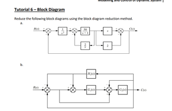
Transcribed Image Text:Tutorial 6-Block Diagram
Reduce the following block diagrams using the block diagram reduction method.
a.
-AA
b.
R(s) +
R(s) +
50
s+1
H₁(s)
G₁(s)
+
S
2
G₂(s)
C(s)
C(s)
Expert Solution
This question has been solved!
Explore an expertly crafted, step-by-step solution for a thorough understanding of key concepts.
Step by stepSolved in 3 steps with 3 images

Knowledge Booster
Learn more about
Need a deep-dive on the concept behind this application? Look no further. Learn more about this topic, electrical-engineering and related others by exploring similar questions and additional content below.Similar questions
- After solving for the total resistance, and the applied voltage being a given for the circuit, the next logical step is to .....? so that individual component voltages and currents can be found.arrow_forwardExplain why the graph does or does not have an Euler circuit. If it does, specify the nodes within the circuit Figure i: An undirected graph has 6 vertices, a through f. 5 vertices are in the form of a regular pentagon, rotated 90 degrees clockwise. Hence, the top vertex becomes the rightmost vertex. From the bottom left vertex, moving clockwise, the vertices in the pentagon shape are labeled: a, b, c, e, and f. Vertex d is above vertex e, below and to the right of vertex c. Undirected edges, line segments, are between the following vertices: b and c; b and a; b and f; b and e; a and c; a and d; a and f; c and d; c and f; d and e; and d and f.arrow_forward1.Utilize an appropriate R-C circuit powered by a 120 V DC source. This RC circuit will be the energy source to power a single Neon Lamp. 2. Neon and other gas-based lamps often require a threshold voltage before they turn "on", i.e. emit light. The neon lamp you will use has a turn-on voltage of 70 V. In the provided LTspice model of such a neon lamp, you can explore how this light turns on and off (i.e. the current through the lamp is high when the lamp is on), when it is powered by a pulsed voltage source. Play around with the pulsed source parameters to investigate the lamp's behavior. However, keep the lamps LIspice parameters fixed (i.e. do not change the attributes of the lamp). 3. Using the RC circuit Power your Neon Lamp so that it turns on every 0.1 seconds (10 Hz frequency). The time for which it remains on is not critical, but should obviously be much less than 0.1 seconds.arrow_forward
- • Write the Verilog code and testbench for the following circuit. Show the waveforms of the simulation using Gtkwave A B. t2 D to search LGarrow_forwardMULTIPLIER 6*4 DESIGNS AND EXPLAIN IT ?arrow_forwardGive an independent set of linear that can ve solved for the current shown. Use the Junction Rulearrow_forward
- Please be detailed and show steps.arrow_forwardc) Using minimum number of components, design a voltage divider which can deliver 1 W at 100V, 2W at -50V and 1.6W at -80V. The voltage source has an internal resistance of 200 Q and supplies a current of 100mA. What is the open - circuit voltage of the voltage source? All resistance in ohm.arrow_forwardIn the circuit , the voltage across the 4 ohm resistor in volts is ___ The circuit is equivalent to a 12V source in series with how many ohms ofresistance? In the circuit, the current through the 6 ohm resistor in amps is ___arrow_forward
- Repeat the design using TFF by making the state diagram of the circuit given below.arrow_forwardResistor and RC Circuits Problem 12: Consider the circuit in the figure, with the current directions defined as shown. There are four resistors in this circuit (R1, R2, R3, and R4) and four batteries with emfs ℰ1 = 15.5 V, ℰ2 = 3.5 V, ℰ3 = 14 V, and ℰ4 = 27.3 V, each with internal resistance given by ri as marked in the figure. Part (a) Calculate the current I1 in amps. Part (b) Calculate the current I2 in amps. Part (c) Calculate the current I3 in amps.arrow_forward"To solve a circuit" means to use the values of potentials and resistances to find all currents passing through, and voltage drops across all elements in the circuit. Create a general procedure to solve any circuit DC circuit with any number of resistors. You may use the Structure Physics Problem-Solving Method as a model.arrow_forward
arrow_back_ios
SEE MORE QUESTIONS
arrow_forward_ios
Recommended textbooks for you
 Introductory Circuit Analysis (13th Edition)Electrical EngineeringISBN:9780133923605Author:Robert L. BoylestadPublisher:PEARSON
 Delmar's Standard Textbook Of ElectricityElectrical EngineeringISBN:9781337900348Author:Stephen L. HermanPublisher:Cengage Learning
 Programmable Logic ControllersElectrical EngineeringISBN:9780073373843Author:Frank D. PetruzellaPublisher:McGraw-Hill Education
 Fundamentals of Electric CircuitsElectrical EngineeringISBN:9780078028229Author:Charles K Alexander, Matthew SadikuPublisher:McGraw-Hill Education
 Electric Circuits. (11th Edition)Electrical EngineeringISBN:9780134746968Author:James W. Nilsson, Susan RiedelPublisher:PEARSON
 Engineering ElectromagneticsElectrical EngineeringISBN:9780078028151Author:Hayt, William H. (william Hart), Jr, BUCK, John A.Publisher:Mcgraw-hill Education,

Introductory Circuit Analysis (13th Edition)
Electrical Engineering
ISBN:9780133923605
Author:Robert L. Boylestad
Publisher:PEARSON

Delmar's Standard Textbook Of Electricity
Electrical Engineering
ISBN:9781337900348
Author:Stephen L. Herman
Publisher:Cengage Learning

Programmable Logic Controllers
Electrical Engineering
ISBN:9780073373843
Author:Frank D. Petruzella
Publisher:McGraw-Hill Education

Fundamentals of Electric Circuits
Electrical Engineering
ISBN:9780078028229
Author:Charles K Alexander, Matthew Sadiku
Publisher:McGraw-Hill Education

Electric Circuits. (11th Edition)
Electrical Engineering
ISBN:9780134746968
Author:James W. Nilsson, Susan Riedel
Publisher:PEARSON

Engineering Electromagnetics
Electrical Engineering
ISBN:9780078028151
Author:Hayt, William H. (william Hart), Jr, BUCK, John A.
Publisher:Mcgraw-hill Education,