
Introductory Circuit Analysis (13th Edition)
13th Edition
ISBN: 9780133923605
Author: Robert L. Boylestad
Publisher: PEARSON
expand_more
expand_more
format_list_bulleted
Related questions
Concept explainers
Question
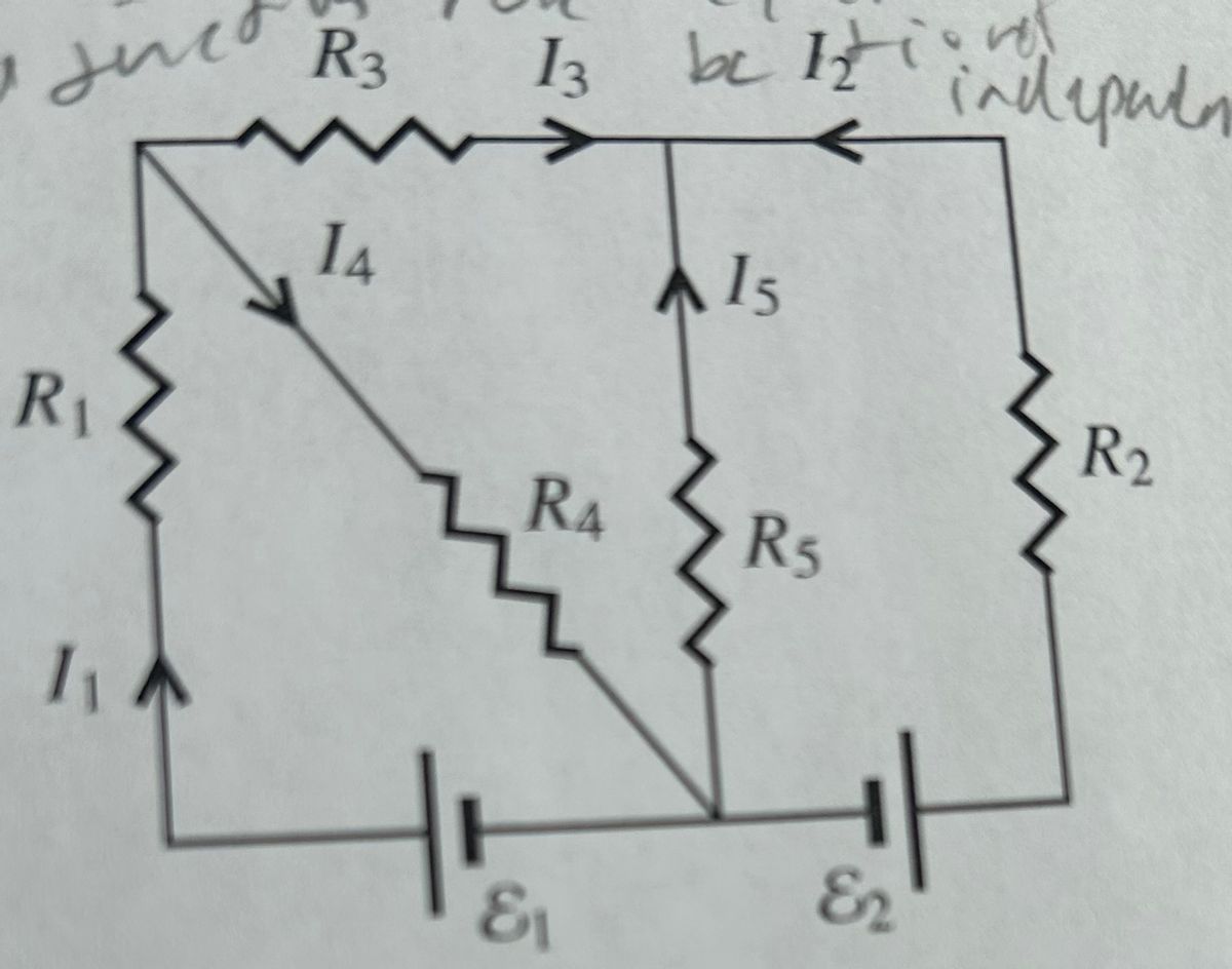
Give an independent set of linear that can ve solved for the current shown. Use the Junction Rule

Transcribed Image Text:sut
R₁
R3
14
13
RA
&₁
be Iztion
A 15
R5
82
independen
R2
Expert Solution
This question has been solved!
Explore an expertly crafted, step-by-step solution for a thorough understanding of key concepts.

Step by stepSolved in 3 steps with 11 images

Knowledge Booster


Learn more about
Need a deep-dive on the concept behind this application? Look no further. Learn more about this topic, electrical-engineering and related others by exploring similar questions and additional content below.Similar questions
- From the diode circuit shown below, If E-40 V and RL=8002, determine the current supplied from the battery, the voltage across the load resistance, and the voltage across diode D2 if all the diodes are silicon with an internal resistance of 1 02. E= D₁ Z D. RL a. The Current supplied by battery is D₂ D3arrow_forwardPlease answer in typing format I need it urgently I will like it please Please ASAP for the likearrow_forwardTrial example of how to use Kirchhoff analysis to determine the initial current in each section along with its direction and the potential difference across the loadarrow_forward
- 2) please solve, will upvote if work is shown!arrow_forwardA diode is a two-terminal, electronic device made using semiconductors that is designed to prevent current from flowing in a particular direction. The symbol is a triangle pointing in the direction that (positive) current is allowed to flow and a wall preventing (positive) current from flowing in the opposite direction: 1: A diode has two modes, "on" and "off". When "on", current flows, and when "off", no current flows. We generally view diodes as either "ideal" or "modeled", as described below. "Ideal" view of a diode + The "ideal" diode is either a short circuit or an open circuit. Specifically, when the voltage across its terminals is negative, no current flows, and when current flows, there is zero voltage across its terminals, as pictured below: Diode "Modeled" view of a diode +51 Diode V Ideal Diode "Off" i=0| + U≤0 + I Therefore, with current i and voltage v defined as shown on the left above, for an "ideal" diode: • Current i cannot be negative. Voltage v cannot be positive. .…arrow_forwardPlease show all work, thank you :)arrow_forward
- A diode is a two-terminal, electronic device made using semiconductors that is designed to prevent current from flowing in a particular direction. The symbol is a triangle pointing in the direction that (positive) current is allowed to flow and a wall preventing (positive) current from flowing in the opposite direction: 1: A diode has two modes, "on" and "off". When "on", current flows, and when "off", no current flows. We generally view diodes as either "ideal" or "modeled", as described below. "Ideal" view of a diode + The "ideal" diode is either a short circuit or an open circuit. Specifically, when the voltage across its terminals is negative, no current flows, and when current flows, there is zero voltage across its terminals, as pictured below: Diode "Modeled" view of a diode +51 Diode V Ideal Diode "Off" i=0| + U≤0 + I Therefore, with current i and voltage v defined as shown on the left above, for an "ideal" diode: • Current i cannot be negative. Voltage v cannot be positive. .…arrow_forwardAfter solving a circuit with ideal diodes (Vf=0), what check is necessary for diodes initially assumed to be on? Off? We must check to see that reverse voltage appears across all diodes assumed to be on, and we must check to see that forward current flows in diodes assumed to be off We must check to see that forward current flows in diodes assumed to be on, and we must check to see that reverse voltage appears across all diodes assumed to be offarrow_forwardFrom the diode circuit shown below, If E=30 V and RL=802, determine the current supplied from the battery, the voltage across the load resistance, and the voltage across diode D2 if all the diodes are silicon with an internal resistance of 1 2. D . RL D4 D3 a. The Current supplied by battery is b. The Voltage across Load resistance RL is c. The Voltage across diode D2 isarrow_forward
- 3. In the following circuits, given source voltage Vs=9V, R1, R2 and R3 all are 1kOhms. Answer the questions by considering the diodes as ideal and practical silicon ones respectively. Vs Vs Vs R2 R2 R2 Vout P D R1 R1 R3 R1 (a) Vout = ? (b) Vp = ? (c) Vp = ? Note: Vp means the voltage at point p. warrow_forwardFor the circuit shown in the figure D, and D2 are identical diode with ideality factor of unity. The thermal voltage is 25mV. Calculate Vr and V, If reverse saturation current is 1pA, find the current, D, D, 50mVarrow_forward
arrow_back_ios
arrow_forward_ios
Recommended textbooks for you
- Introductory Circuit Analysis (13th Edition)Electrical EngineeringISBN:9780133923605Author:Robert L. BoylestadPublisher:PEARSON
 Delmar's Standard Textbook Of ElectricityElectrical EngineeringISBN:9781337900348Author:Stephen L. HermanPublisher:Cengage Learning
 Programmable Logic ControllersElectrical EngineeringISBN:9780073373843Author:Frank D. PetruzellaPublisher:McGraw-Hill Education
  Fundamentals of Electric CircuitsElectrical EngineeringISBN:9780078028229Author:Charles K Alexander, Matthew SadikuPublisher:McGraw-Hill Education
 Electric Circuits. (11th Edition)Electrical EngineeringISBN:9780134746968Author:James W. Nilsson, Susan RiedelPublisher:PEARSON
 Engineering ElectromagneticsElectrical EngineeringISBN:9780078028151Author:Hayt, William H. (william Hart), Jr, BUCK, John A.Publisher:Mcgraw-hill Education,
Introductory Circuit Analysis (13th Edition)
Electrical Engineering
ISBN:9780133923605
Author:Robert L. Boylestad
Publisher:PEARSON
Delmar's Standard Textbook Of Electricity
Electrical Engineering
ISBN:9781337900348
Author:Stephen L. Herman
Publisher:Cengage Learning
Programmable Logic Controllers
Electrical Engineering
ISBN:9780073373843
Author:Frank D. Petruzella
Publisher:McGraw-Hill Education
Fundamentals of Electric Circuits
Electrical Engineering
ISBN:9780078028229
Author:Charles K Alexander, Matthew Sadiku
Publisher:McGraw-Hill Education
Electric Circuits. (11th Edition)
Electrical Engineering
ISBN:9780134746968
Author:James W. Nilsson, Susan Riedel
Publisher:PEARSON
Engineering Electromagnetics
Electrical Engineering
ISBN:9780078028151
Author:Hayt, William H. (william Hart), Jr, BUCK, John A.
Publisher:Mcgraw-hill Education,