
Introductory Circuit Analysis (13th Edition)
13th Edition
ISBN: 9780133923605
Author: Robert L. Boylestad
Publisher: PEARSON
expand_more
expand_more
format_list_bulleted
Related questions
Question
Solve by hand do not use AI
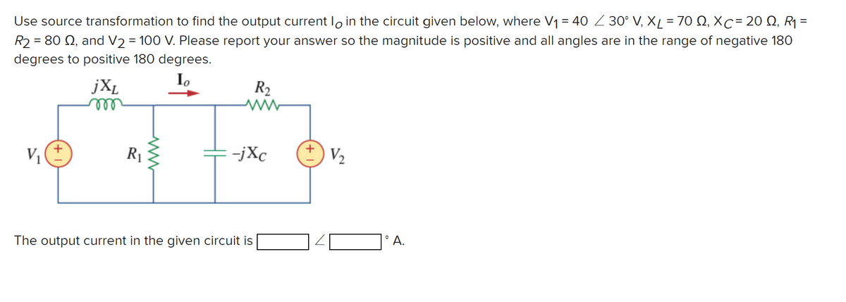

Transcribed Image Text:Use source transformation to find the output current lo in the circuit given below, where V₁ = 40 30° V, XL = 700, XC = 20, R₁ =
R2=80 Q2, and V2 = 100 V. Please report your answer so the magnitude is positive and all angles are in the range of negative 180
degrees to positive 180 degrees.
jXL
m
V₁
R₁
www
Io
R₂
ww
=-jxc
+
V₂
The output current in the given circuit is
1° A.
Expert Solution
This question has been solved!
Explore an expertly crafted, step-by-step solution for a thorough understanding of key concepts.

Step by stepSolved in 2 steps with 3 images

Knowledge Booster

Similar questions
- Vi is a sinusoid signal of 8 Vp-p and f = 1 kHz. Vref = 2 V and V1 = 5 V and V2 = -1V. Assume that V1 is connected to pin7 of op-amp 741 and V2 is connected to pin 4. The output Vo will be, * V1 Vo 741 Vret O A square wave of 6 Vp-p, 1 kHz A rectangular wave of 6 Vp-p, 1 kHz A triangular wave of 6 Vp-p, 1 kHz A sinusoid wave of 8 Vp-p, 1 kHz A rectangular wave of 4 Vp-p, 1 kHz A square wave of 8 Vp-p, 1 kHz A sawtooth wave of 6 Vp-p, 1 kHz O A sinusoid wave of 6 Vp-p, 1 kHzarrow_forward6. What is the output voltage for the LM317 Circuit when R10 is set at 00 and at 5 KQ? a. 0 = b. 5 k= 35 V 7. Use ideal parts for D2 and the SCR. What is the voltage and waveform at H1 when the pot is at 0, 250, and 500 ? Draw the waveform a. 02= v wave form b. 250 = v wave form c. c. 500 = _v, wave form C3 U3 LM317 VIN VOUT ADJ C4 V1 120 V R9 500 R11 10 k R8 220 R10 D2 +V Out H1 C5 R12 100arrow_forwardNegative Clamping Circuit: Can you explain why the output voltage gets shifted down logically?arrow_forward
- The ratio of the forward voltage to the forward current is called the characteristic impedance? What is forward voltage? What is the forward current? What is characteristic impedance?arrow_forwardProblem F Design component values to produce a 2.4 kHz square wave. Assume the op amp output can go to the supply voltages. Cap: 1Exx Resistors: 100 < R < 100k C1 tl R1 +10V IC1 →° -10V Hli R2 R3arrow_forwardOUTPUT VOLTAGE (V) 2.0 1.8 1.6 1.0 0.8 0.6 0.2 0 <-50 a. TMP35 b. TMP36 c. TMP37 +Vs = 3V -25 0 50 25 TEMPERATURE (°C) 75 Figure 6. Output Voltage vs. Temperature 100 b 125 00337-007 Using the appropriate curve, develop a linear equation for the output temperature as a function of voltage.arrow_forward
- Find Vout in terms of waveform generator.arrow_forwardsolve the question and demonstrate alor please I want to understand prefectly. Thank you.arrow_forwardC'uk Converter Design A C'uk converter has an input of 12 V and is to have an output of - 24 V supplying a 60 W load. Select the duty ratio, the switching frequency, the inductor sizes such that the change in inductor currents is no more than 12 percent of the average inductor current, the output ripple voltage is no more than 1.5 percent, and the ripple voltage across C1 is no more than 3 percent.arrow_forward
- The data-input and data-select waveforms in Figure 7 are applied to the multiplexer. Determine the output waveform F in relation to the inputs.arrow_forward2. figure out the gain of each of the 3 sections of this circuit at the oscillation frequency. The three sections are (R1, C1, and OP1), (R2, C2 and OP2) and (R3 and C3). frequency = 100 khz impedance of capacitor = 15.9 ohms.arrow_forwardThe subject is Power Electronics & Power Systems. Please write in the clear handwritten, put all formula required for the Question.MAKE YOUR ANSWER SHORT & SIMPLE PLEASE.arrow_forward
arrow_back_ios
SEE MORE QUESTIONS
arrow_forward_ios
Recommended textbooks for you
- Introductory Circuit Analysis (13th Edition)Electrical EngineeringISBN:9780133923605Author:Robert L. BoylestadPublisher:PEARSON
 Delmar's Standard Textbook Of ElectricityElectrical EngineeringISBN:9781337900348Author:Stephen L. HermanPublisher:Cengage Learning
 Programmable Logic ControllersElectrical EngineeringISBN:9780073373843Author:Frank D. PetruzellaPublisher:McGraw-Hill Education
  Fundamentals of Electric CircuitsElectrical EngineeringISBN:9780078028229Author:Charles K Alexander, Matthew SadikuPublisher:McGraw-Hill Education
 Electric Circuits. (11th Edition)Electrical EngineeringISBN:9780134746968Author:James W. Nilsson, Susan RiedelPublisher:PEARSON
 Engineering ElectromagneticsElectrical EngineeringISBN:9780078028151Author:Hayt, William H. (william Hart), Jr, BUCK, John A.Publisher:Mcgraw-hill Education,
Introductory Circuit Analysis (13th Edition)
Electrical Engineering
ISBN:9780133923605
Author:Robert L. Boylestad
Publisher:PEARSON
Delmar's Standard Textbook Of Electricity
Electrical Engineering
ISBN:9781337900348
Author:Stephen L. Herman
Publisher:Cengage Learning
Programmable Logic Controllers
Electrical Engineering
ISBN:9780073373843
Author:Frank D. Petruzella
Publisher:McGraw-Hill Education
Fundamentals of Electric Circuits
Electrical Engineering
ISBN:9780078028229
Author:Charles K Alexander, Matthew Sadiku
Publisher:McGraw-Hill Education
Electric Circuits. (11th Edition)
Electrical Engineering
ISBN:9780134746968
Author:James W. Nilsson, Susan Riedel
Publisher:PEARSON
Engineering Electromagnetics
Electrical Engineering
ISBN:9780078028151
Author:Hayt, William H. (william Hart), Jr, BUCK, John A.
Publisher:Mcgraw-hill Education,