close
Homework Help is Here – Start Your Trial Now!
arrow_forward
Literature guides
Concept explainers
Writing guide
Popular textbooks
Popular high school textbooks
Popular Q&A
Business
Accounting
Business Law
Economics
Finance
Leadership
Management
Marketing
Operations Management
Engineering
AI and Machine Learning
Bioengineering
Chemical Engineering
Civil Engineering
Computer Engineering
Computer Science
Cybersecurity
Data Structures and Algorithms
Electrical Engineering
Mechanical Engineering
Language
Spanish
Math
Advanced Math
Algebra
Calculus
Geometry
Probability
Statistics
Trigonometry
Science
Advanced Physics
Anatomy and Physiology
Biochemistry
Biology
Chemistry
Earth Science
Health & Nutrition
Health Science
Nursing
Physics
Social Science
Anthropology
Geography
History
Political Science
Psychology
Sociology
learn
writing tools
expand_more
plus
study resources
expand_more
Log In
Sign Up
expand_more
menu
SEARCH
Homework help starts here!
ASK AN EXPERT
ASK
Engineering
Electrical Engineering
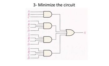
3- Minimize the circuit D ABC ABCDBCD ARCIO X
BUY
Power System Analysis and Design (MindTap Course List)
6th Edition
ISBN:
9781305632134
Author: J. Duncan Glover, Thomas Overbye, Mulukutla S. Sarma
Publisher:
Cengage Learning
expand_less
1 Introduction
2 Fundamentals
3 Power Transformers
4 Transmission Line Parameters
5 Transmission Lines: Steady-state Operation
6 Power Flows
7 Symmetrical Faults
8 Symmetrical Components
9 Unsymmetrical Faults
10 System Protection
11 Transient Stability
12 Power System Controls
13 Transmission Lines: Transient Operation
14 Power Distribution
expand_more
Chapter Questions
expand_more
Problem 3.1MCQ: The Ohms law for the magnetic circuit states that the net magnetomotive force (mmf) equals the...
Problem 3.2MCQ: For an ideal transformer, the efficiency is (a) 0 (b) 100 (c) 50
Problem 3.3MCQ: For an ideal 2-winding transformer, the ampere-turns of the primary winding, N1I1 is equal to the...
Problem 3.4MCQ: An ideal transformer has no real or reactive power loss. (a) True (b) False
Problem 3.5MCQ: For an ideal 2-winding transformer, an impedance Z2 connected across winding 2 (secondary) is...
Problem 3.6MCQ: Consider Figure 3.4. For an ideal phase-shifting transformer, the imda nce is unchanged when it is...
Problem 3.7MCQ: Consider Figure 3.5. Match the following, those on the left to those on the right. (i) Im (a)...
Problem 3.8MCQ: The units of admittance, conductance, and susceptance are siemens. (a) True (b) False
Problem 3.9MCQ: Match the following: (i) Hysteresis loss (a) Can be redud by constructing the core with laminated...
Problem 3.10MCQ: For large power transformers rated more than 500 kVA, the winding resistances, which are small...
Problem 3.11MCQ: For a short-circuit test on a 2-winding transformer, with one winding shorted, can you apply the...
Problem 3.12MCQ: The per-unit quantity is always dimensionless. (a) True (b) False
Problem 3.13MCQ: Consider the adopted per-unit system for the transformers. Specify true or false for each of the...
Problem 3.14MCQ: The ideal transformer windings are eliminated from the per-unit equivalent circuit of a transformer....
Problem 3.15MCQ: To convert a per-unit impedance from old to new base values, the equation to be used is...
Problem 3.16MCQ: In developing per-unit circuits of systems such as the one shown in Figure 3.10. when moving across...
Problem 3.17MCQ
Problem 3.18MCQ
Problem 3.19MCQ: With the American Standard notation, in either a Y-or-Y transformer, positive- sequen quantities on...
Problem 3.20MCQ
Problem 3.21MCQ: In order to avoid difficulties with third-harmonic exciting current, which three-phase transformer...
Problem 3.22MCQ: Does an open connection permit balanced three-phase operation? - (a) Yes (b) No
Problem 3.23MCQ: Does an open- operation, the kVA rating compared to that of the original thr-phase bank is (a) 2/3...
Problem 3.24MCQ: It is stated that (i) balanced three-phase circuits can be solved in per unit on a per-phase basis...
Problem 3.25MCQ: In developing per-unit equivalent circuits for three-phase transformers. under balanced three-phase...
Problem 3.26MCQ: In per-unit equivalent circuits of practical three-phase transformers, under balanced thr-phase...
Problem 3.27MCQ
Problem 3.28MCQ
Problem 3.29MCQ: For developing per-unit equivalent circuits of single-phase three-winding transformer, a common...
Problem 3.30MCQ
Problem 3.31MCQ
Problem 3.32MCQ
Problem 3.33MCQ: The direct electrical connection of the windings allows transient over voltages to pass through the...
Problem 3.34MCQ: Consider Figure 3.25 of the text for a transformer with off-nominal turns ratio. (i) The per-unit...
Problem 3.1P: (a) An ideal single-phase two-winding transformer with turns ratio at=N1/N2 is connected with a...
Problem 3.2P: An ideal transformer with N1=1000andN2=250 is connected with an impedance Z22 across winding 2. If...
Problem 3.3P: Consider an ideal transformer with N1=3000andN2=1000 turns. Let winding 1 be connected to a source...
Problem 3.4P: A single-phase 100-kVA,2400/240-volt,60-Hz distribution transformer is used as a step-down...
Problem 3.5P
Problem 3.6P
Problem 3.7P: Consider a source of voltage v(t)=102sin(2t)V, with an internal resistance of 1800. A transformer...
Problem 3.8P
Problem 3.9P
Problem 3.10P: A single-phase step-down transformer is rated 13MVA,66kV/11.5kV. With the 11.5 kV winding...
Problem 3.11P: For the transformer in Problem 3.10. The open-circuit test with 11.5 kV applied results in a power...
Problem 3.12P
Problem 3.13P: A single-phase 50-kVA,2400/240-volt,60-Hz distribution transformer has a 1-ohm equivalent leakage...
Problem 3.14P: A single-phase 50-kVA,2400/240-volt,60-Hz distribution transformer is used as a step-down...
Problem 3.15P: Rework Problem 3.14 if the transformer is delivering rated load at rated secondary voltage and at...
Problem 3.16P: A single-phase, 50-kVA,2400/240-V,60-Hz distribution transformer has the following parameters:...
Problem 3.17P: The transformer of Problem 3.16 is supplying a rated load of 50 kVA at a rated secondary voltage of...
Problem 3.18P: Using the transformer ratings as base quantities, work Problem 3.13 in per-unit.
Problem 3.19P: Using the transformer ratings as base quantities. work Problem 3.14 in per-unit.
Problem 3.20P: Using base values of 20 kVA and 115 volts in zone 3, rework Example 3.4.
Problem 3.21P
Problem 3.22P: A balanced Y-connected voltage source with Eag=2770volts is applied to a balanced-Y load in parallel...
Problem 3.23P: Figure 3.32 shows the oneline diagram of a three-phase power system. By selecting a common base of...
Problem 3.24P: For Problem 3.18, the motor operates at full load, at 0.8 power factor leading, and at a terminal...
Problem 3.25P: Consider a single-phase electric system shown in Figure 3.33. Transformers are rated as follows:...
Problem 3.26P: A bank of three single-phase transformers, each rated 30MVA,38.1/3.81kV, are connected in Y- with a...
Problem 3.27P: A three-phase transformer is rated 1000MVA,220Y/22kV. The Y-equivalent short-circuit impedance,...
Problem 3.28P: For the system shown in Figure 3.34. draw an impedance diagram in per unit by choosing 100 kVA to be...
Problem 3.29P: Consider three ideal single-phase transformers (with a voltage gain of ) put together as ...
Problem 3.30P: Reconsider Problem 3.29. If Va,VbandVc are a negative-sequence set, how would the voltage and...
Problem 3.31P
Problem 3.32P: Determine the positive- and negative-sequence phase shifts for the three- phase transformers shown...
Problem 3.33P: Consider the three single-phase two-winding transformers shown in Figure 3.37. The high-voltage...
Problem 3.34P: Three single-phase, two-winding transformers, each rated 450MVA,20kV/288.7kV, with leakage reactance...
Problem 3.35P: Consider a bank of this single-phase two-winding transformers whose high-voltage terminals are...
Problem 3.36P: Three single-phase two-winding transformers, each rated 25MVA,34.5/13.8kV, are connected to form a...
Problem 3.37P: Three single-phase two-winding transformers, each rated 25MVA,54.2/5.42kV, are connected to form a...
Problem 3.38P: Consider a three-phase generator rated 300MVA,23kV, supplying a system load of 240 MA and 0.9 power...
Problem 3.39P: The leakage reactance of a three-phase, 300-MVA,230Y/23-kV transformer is 0.06 per unit based on its...
Problem 3.40P
Problem 3.41P: Consider the single-line diagram of the power system shown in Figure 3.38. Equipment ratings are...
Problem 3.42P: For the power system in Problem 3.41, the synchronous motor absorbs 1500 MW at 0.8 power factor...
Problem 3.43P: Three single-phase transformers, each rated 10MVA,66.4/12.5kV,60Hz, with an equivalent series...
Problem 3.44P: A 130-MVA,13.2-kV three-phase generator, which has a positive-sequence reactance of 1.5 per unit on...
Problem 3.45P: Figure 3.39 shows a oneline diagram of a system in which the three-phase generator is rated 300 MVA,...
Problem 3.46P: The motors M1andM2 of Problem 3.45 have inputs of 120 and 60 MW, respectively, at 13.2 kV, and both...
Problem 3.47P: Consider the oneline diagram shown in Figure 3.40. The three-phase transformer bank is made up of...
Problem 3.48P: With the same transformer banks as in Problem 3.47, Figure 3.41 shows the oneline diagram of a...
Problem 3.49P: Consider the single-Line diagram of a power system shown in Figure 3.42 with equipment ratings...
Problem 3.50P: A single-phase three-winding transformer has the following parameters: Z1=Z2=Z3=0+j0.05,Gc=0, and...
Problem 3.51P: The ratings of a three-phase three-winding transformer are Primary(1): Y connected 66kV,15MVA...
Problem 3.52P
Problem 3.53P: The ratings of a three-phase, three-winding transformer are Primary: Y connected, 66kV,15MVA...
Problem 3.54P: An infinite bus, which is a constant voltage source, is connected to the primary of the...
Problem 3.55P: A single-phase l0-kVA,2300/230-volt,60-Hz two-winding distribution transformer is connected as an...
Problem 3.56P: Three single-phase two-winding transformers, each rated 3kVA,220/110volts,60Hz, with a 0.10 per-unit...
Problem 3.57P: A two-winding single-phase transformer rated 60kVA,240/1200V,60Hz, has an efficiency of 0.96 when...
Problem 3.58P: A single-phase two-winding transformer rated 90MVA,80/120kV is to be connected as an autotransformer...
Problem 3.59P
Problem 3.60P: PowerWorid Simulator case Problem 3_60 duplicates Example 3.13 except that a resistance term of 0.06...
Problem 3.62P: Rework Example 3.12 for a+10 tap, providing a 10 increase for the high-voltage winding.
Problem 3.63P: A 23/230-kV step-up transformer feeds a three-phase transmission line, which in turn supplies a...
Problem 3.64P: The per-unit equivalent circuit of two transformers Ta and Tb connected in parallel, with the same...
Problem 3.65P: Reconsider Problem 3.64 with the change that now Tb includes both a transformer of the same turns...
Problem ACSQ: What are the advantages of correctly specifying a transformer most Suita ble for its application?
Problem BCSQ: Why is it important to reduce the moisture within a transformer to acceptable levels during...
Problem CCSQ: What should be the focus of transformer preventive maintenance efforts?
format_list_bulleted
See similar textbooks
Question
Transcribed Image Text:
3- Minimize the circuit D ABC ABCDBCD ARCIO X
Expert Solution
This question has been solved!
Explore an expertly crafted, step-by-step solution for a thorough understanding of key concepts.
See solution
Check out a sample Q&A here
Step by step
Solved in 2 steps with 1 images
See solution
Check out a sample Q&A here
Knowledge Booster
Similar questions
arrow_back_ios
arrow_forward_ios
can i you solve just problem d
arrow_forward
for the given circuit find p & q for the load as shown
arrow_forward
R₁ =1292 Igc = 0.16A IDC = Problem #21) Determine the source current Ipc and the resistor voltage V4 as shown in the following circuit using the Reduce and Return Method if the source voltage is Vpc = 72 volts. R₂=402 R₁ =1552 R₁=4592 0.16 IDC =. V₁=. 2 (A) 36 (A) (V)
arrow_forward
Reference 7 segment display: Solve for the segments: "d, e, and f." Show your work 1. KMAPs 2. Reduced equation to lite up the segment 3. Describe the operation of Lab 12 4. If you were to add a 4th seven-segment, Describe your design process.
arrow_forward
Which of the following is NOT a circuit in the graph? * A в F E ABFEA BFDCB None of the Above
arrow_forward
Find Vdc, Irms, Idc, Imax, Pdc
arrow_forward
Question 11 Use a Karnaugh map to find the minimum SOP form for the following expression: A'B'C'D + B'C'D' + A'BC'D' + ABC'D' + A'B'CD + AB'CD + A'B'CD' + A'BCD' + ABCD' + AB'CD' + AB'C'D A'B' + C'D' + AB' + CD' O {A'B' + C'D' + AB' + CD'}' O A'B' + C'D' B' + D'
arrow_forward
2022 - X Deeng3345-Hwk1-Sp2023 - Spring X M (no subject) - ss38313@georgias x e/content/714122/viewContent/11107332/View?ou-714122 Bi une inductor. Zc= Reflect in ePortfolio Given the following circuit, apply the current divider rule (CDR) to find the current in R₁ www Is Download ZL mm IL R₂ 4 + Print Consider: R₁ R₂ = 122, Zc = -j1 22, ZL=j1 22, Is=2 <20° Amp Activity Details DELL
arrow_forward
Analyze and redraw the complex circuit into a simple circuit diagram. At circuits #1 and #2, solve for: a. Rt b.It c.V at 5 ohm resistor d.I at 5 ohm resistor e.P at 5 ohm resistor
arrow_forward
Use nodal analysis to solve for Va ,Vb Vc ,VG , l1 , L2 , L3 , V1 , V2 and V3
arrow_forward
Precision VCIS for Ground-Referenced Load - Example Problem F2 Vcco a. Determine the load Vcc o Rcs current R1 Vcco- b. Determine the range of loads that will keep |VCE| > 0.6V V+ R2 Q1 V- R2 Lo-Vcc RLoad R, R2 Rcs Vcc /-Vcc 20k 80k 390 12V/-12V +
arrow_forward
7. For the bridge circuit given, Vsupply = 70V, and R₁= 2002, R₂=4022, R3=37.50, R4=509 and R5= 1000. For Delta to wye conversion, the following assumption is made Ra is between R₁ and R₂; R₁ is between R₂ and R5; Rc is between R5 and R₁ • What the voltage V5? 5 Volts 10 Volts 25 Volts 15 Volts Vsupply 100
arrow_forward
arrow_back_ios
SEE MORE QUESTIONS
arrow_forward_ios
Recommended textbooks for you
Power System Analysis and Design (MindTap Course ...
Electrical Engineering
ISBN:
9781305632134
Author:
J. Duncan Glover, Thomas Overbye, Mulukutla S. Sarma
Publisher:
Cengage Learning
Delmar's Standard Textbook Of Electricity
Electrical Engineering
ISBN:
9781337900348
Author:
Stephen L. Herman
Publisher:
Cengage Learning
SEE MORE TEXTBOOKS